If you are a Python programmer, and need a simple USB interface for some hardware, read on…
FTDI are well known for their USB-to-serial chips, but the later models (such as FT2232C and FT232H) have various other capabilities; when combined with Python, you get a simple yet powerful method of controlling & monitoring a wide variety of hardware devices.
Hardware
Various FTDI-equipped modules and cables are available.
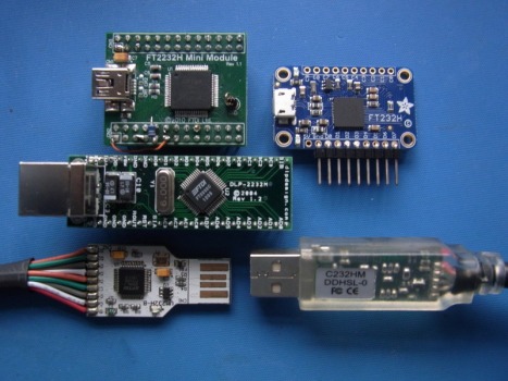
A few points to bear in mind:
- The module may need to have some of its pins linked together, otherwise it won’t power up.
- If the module has a 5 Volt output pin, take care when connecting it up; if mis-connected, a sizeable current may flow, causing significant damage.
- Each FTDI device has a unique set of capabilities; check the datasheet to make sure the part has the facilities you need.
Device driver
As standard, when an FTDI device is plugged into a Windows PC, the operating system loads the default Virtual Com Port driver, that can only handle asynchronous serial (RS232-type) protocols. However, we want to be a bit more adventurous, so need to substitute the ‘d2xx’ driver, available from the FTDI drivers page. A quick way to check which driver is active is to look at the Device Manager; if the FTDI part appears as a COM port, it is asynchronous-only.
Use ‘pip’ to install a Python library that will access the d2xx driver; there are several available (such as pyftdi, pylibftdi) but the only one that worked seamlessly with Python 2.7 and 3.x on my systems was the simplest: ftd2xx, which is just a CTYPES wrapper round the d2xx API
pip install ftd2xx
A quick check to see if all is well (Python 2.7 or 3.x):
import sys, ftd2xx as ftd
d = ftd.open(0)    # Open first FTDI device
print(d.getDeviceInfo())
This should print some dictionary entries for the device, e.g.
{'serial': 'FT28C9AHA', 'type': 4L, 'id': 67330064L, 'description': 'DLP2232M A'}
If this fails, it is usually because the device is still using the VCP driver, or the Python library can’t find the necessary FTDI files (ftd2xx.lib, and ftd2xx.dll or ftd2xx64.dll); they need to be somewhere on the executable PATH.
Linux drivers are discussed in the next post.
Pinout
Before sending any data to the device, we need to establish which pins does what, as all pin functions are pre-assigned. Each chip has 1 or more ‘channels’, i.e. protocol engines, so a 2-channel device can drive 2 separate protocol streams, though there may be a limitation on the protocols a channel can handle. Each channel is assigned to one or more ports, which are usually 8-bit, but may have as many as 10 or as few as 4 bits. The first port of the first channel is identified as ADBUS; if that channel has a second port, it would be ACBUS. The first port of the second channel (if present) is BDBUS, the second port of that channel would be BCBUS.
The serial I/O functions are generally constrained to the lower few bits of the first port, the rest of the lines act as general status or handshake I/O. For example, the 2-channel FT2232C device channel A has pins ADBUS 0 – 7 and ACBUS 0 – 3:
CHANNEL A                           CHANNEL B
PIN NAME UART   BIT-BANG  MPSSE     PIN NAME UART   BIT-BANG  MPSSE
ADBUS0   TxD    D0        TCK/SK    BDBUS0   TxD    D0        -
ADBUS1   RxD    D1        TDI/DO    BDBUS1   RxD    D1        -
ADBUS2   RTS    D2        TDO/DI    BDBUS2   RTS    D2        -
ADBUS3   CTS    D3        TMS/CS    BDBUS3   CTS    D3        -
ADBUS4   DTR    D4        GPIOL0    BDBUS4   DTR    D4        -
ADBUS5   DSR    D5        GPIOL1    BDBUS5   DSR    D5        -
ADBUS6   DCD    D6        GPIOL2    BDBUS6   DCD    D6        -
ADBUS7   RI     D7        GPIOL3    BDBUS7   RI     D7        -
ACBUS0   TXDEN  WR        GPIOH0    BCBUS0   TXDEN  WR        -
ACBUS1   SLEEP  RD        GPIOH1    BCBUS1   SLEEP  RD        -
ACBUS2   RXLED  IORDY     GPIOH2    BCBUS2   RXLED  IORDY     -
ACBUS3   TXLED  OSC       GPIOH3    BCBUS3   TXLED  OSC       -
The GPIOL and GPIOH prefixes refer to the low & high byte output commands that we’ll encounter later when using MPSSE mode for synchronous protocols; also note that channel B is unusable in that mode.
A possible source of confusion is that pins 1 and 2 in MPSSE mode are identified as TDI/DO and TDO/DI, implying that they can act as inputs or outputs. This is incorrect: in MPSSE mode, pin 1 is normally an output, and pin 2 is an input. The reason for the TDI and TDO labels is that they refer to the JTAG protocol, which is defined from the point of view of the device being controlled, not the controller – so the DO and DI labels apply in normal usage.
Also note that the device has a tendency to keep its previous settings, even after a reset. For this reason, all programs using the ftd2xx library normally start by clearing everything in the device to zero, just in case a preceding program has left some settings active. For simplicity, the code given below ignores this requirement, and assumes the device has been re-plugged just before the code was run.
Bitbang mode: toggling an I/O pin
‘bitbashing’ which FTDI call ‘bitbanging’, refers to driving the I/O pins directly, rather than using an I/O protocol embedded in the device.
The FTDI device powers up in ‘reset mode’ and must be set to bitbang mode using the setBitmode function. One advantage of using the Python ftd2xx library is that the function arguments are as documented in the FTDI ‘D2XX Programmers Guide’:
OP = 0x01            # Bit mask for output D0
d.setBitMode(OP, 1)  # Set pin as output, and async bitbang mode
d.write(str(OP))     # Set output high
d.write(str(0))      # Set output low
Having set our chosen pin as an output, and enabled bitbang mode, writing a string to the device handle will set its state. The ‘write’ functions returns the number of characters written, which is 1 in this case. If your application involves sending out a succession of O/P pulses, you’ll want to know how fast the operation is; sending the following commands:
d.write(chr(OP)); d.write(chr(0))
results in a positive pulse somewhere between 500 microseconds and 2 milliseconds wide. This will be too variable and too slow for many applications, so an alternative is to write a string containing multiple data values, e.g.
d.write(chr(OP) + chr(0))
This results in a pulse 50 nanoseconds wide, which is probably too narrow for most applications, however in theory you can just duplicate a command to stretch it out, for example to generate a pulse of 200 nanoseconds:
d.write(chr(OP)*4 + chr(0))
This approach is somewhat inefficient, and works fine on Python 2.7, but not on Python 3.x; if you connect an oscilloscope to the output, you’ll see a couple of cycles of 10 MHz square-wave, instead of a single broad pulse. Using a USB analyser to monitor the data, it is apparent that the code is sending the bytes 01 00 01 00 01 instead of 01 01 01 01 00; the length is correct, but the data values are wrong, because of the different ways Python 2.7 and 3.x store their strings.
Byte values in Python 2.7 and 3.x
The default string type can’t be used for byte data in 3.x, as the characters are 16-bit Unicode values, not bytes. There are various ways round the problem, the simplest is to force the string type to binary:
d.write(b"\x01\x01\x01\x01\x00")
This is fine for preformatted strings, but gets rather messy if the data is being computed on-the-fly. There are plenty of alternative suggestions on the Internet, but many don’t work in special cases, such as bit 7 being set. The ‘bytearray’ type would be useful, except that it is rejected as an unknown type by the ftd2xx library. The ‘bytes’ datatype is good on v3, but works very differently on v2.7, so for my development I reluctantly decided to store all outgoing data as lists of integers, with a version-dependant conversion function on writing, e.g.
def ft_write(d, data):
    s = str(bytearray(data)) if sys.version_info<(3,) else bytes(data)
    return d.write(s)

ft_write(d, [OP]*4 + [0])
Slowing down output transitions
Sending multiple output commands to slow down the output transitions is quite inefficient, and unworkable for really long pulses. A better alternative is to program the baud rate generator (the same generator as used for serial communications), which synchronises the transitions, e.g.
d.setBaudRate(9600)
ft_write(d, (OP, 0))
The FTDI Application Note states that the output is clocked at 16 times the baud rate, so 9600 baud should result in a timing of 6.51 microseconds per bit. However, on an FT2232H module the time was measured as 20.825 microseconds, so that logic seemingly doesn’t apply to all modules.
Reading input pins
Finally we get to read some data in:
print(d.read(1))
The length of 1 returns an 8-bit value corresponding to the I/O pin states; as before, the returned type depends on the Python version, so I convert it to a list of integers:
def ft_read(d, nbytes):
    s = d.read(nbytes)
    return [ord(c) for c in s] if type(s) is str else list(s)

print(ft_read(d, 1))
Unused inputs float high, and the last output command drove the ADBUS0 output low, so the value printed is 254 in a list, [254].
You can implement quite complex protocols using simple I/ O commands; write-cycles can be chained to output complex sequences, but there is quite a speed-penalty every time a read-cycle has to be interleaved. In recognition of this, many FTDI chips have a more complex capability, which they call MPSSE (Multi-Protocol Synchronous Serial Engine); that’ll be the subject of a later blog post…
See the next post to run the code on Linux…
Copyright (c) Jeremy P Bentham 2018. Please credit this blog if you are using the information or software in it.

Thank you for your indication on the problem. Though I didn’t get any oscilloscope to fine dig into the debugging, I did have a rewind of both the wiring and coding. It turned out to be that I wrongly connected the AD0 to SDA and AD1 to SCL of the apds9960 module which is a bad practice. Your articles on ftdi device is really of great help to building of my little project, as I’m just a novice to the hardware world and mainly self-taught on all the knowledge in need. I was desperately searching the web for tutorials as well as examples on ftdi device in mpsse/i2c mode, would you mind being bothered to add another part to your blog on i2c mode dissection at your leisure?
LikeLiked by 1 person
Would like very much to add i2c, unfortunately there is a long list of things to write about, and very little spare time…
LikeLike
Thanks for your examples of how to use some of the FTDI libraries. Even though I’m not using them in Python they helped me a lot.
I’m not a Python programmer but in Perl the reliable way to convert between internal and C-type datatypes is to use pack() and unpack(). Those are available in Python, too. The format code for python-integer to unsigned-char seems to be ‘B’ so you would use char = pack(‘B’, int). Not sure if that might solve the 2.7 vs. 3.x problems?
LikeLike