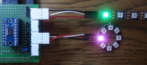
WS2812B LEDs (‘NeoPixels’) are intelligent devices, that can be programmed to a specific 24-bit red, green & blue (RGB) colour, by a pulse train on a single wire. They are capable of being daisy-chained, so a single pulse line can drive a large number of devices.
The programming pulses have to be accurately timed to within fractions of a microsecond, so conventional Raspberry Pi techniques are of limited use; they can only handle a small number of pulse channels, driving a maximum of 1 or 2 strings of LEDs, which is insufficient for a complex display.
This blog post describes a new technique that uses the RPi Secondary Memory Interface (SMI) to drive 8 or 16 channels with very accurate timing. No additional hardware is needed, apart from a 3.3 to 5V level-shifter, that is required for all NeoPixel interfaces.
Pulse shape
To set one device, it is necessary to send 24 pulses with specific widths into its input; they represent green bits G7 to G0, red bits R7 to R0, and blue bits B7 to B0, in that order. If you send more than 24 bits, the extra will emerge from the data output pin, which can drive the data input of the next device in the chain, so to drive ‘n’ LEDs, it is necessary to send n * 24 pulses, without any sizeable gaps in the transmission. If the data line is held low for the ‘reset’ time (or longer), the next transmission will restart at the first LED. Here is a waveform for 2 LEDs in a chain, the first being set to red (RGB 240,0,0) the second to green (RGB 0,240,0).

It is just about possible to see the 0 and 1 pulses on the oscilloscope trace above, here is a zoomed-in section of that trace, to show the varying pulse width more clearly.

You can see that the pulses for the second LED are offset by about 200 nanoseconds from those of the first LED; this is because the first LED is regenerating the signal, rather than just copying the input to output.
The precise definition of a 0/1/reset pulse depends which version of the LED you are using, but the commonly-accepted values in microseconds (us) are:
0:   0.4 us high, 0.85 us low, tolerance +/- 0.15 us
1:   0.8 us high, 0.45 us low, tolerance +/- 0.15 us
RST: at least 50 us (older devices) or 300 us (newer devices)
To simplify the code, we can tweak the values slightly, whilst still remaining in the tolerance band, so my code generates a ‘0’ pulse as 0.4 us high, 0.8 us low, and a ‘1’ pulse as 0.8 us high, 0.4 us low.
Generating the pulses
Since the pulses have to be quite accurately timed, and the Raspberry Pi has no specific hardware for pulse generation, the pulse width modulation (PWM) or audio interfaces are generally used, but this imposes a significant limitation on the number of LED channels that can be supported. I’m using the Secondary Memory Interface (SMI) instead, which could provide up to 18 channels, though my software only supports 8 or 16.
If you are interested in learning more about SMI, I have written a detailed post here, but the key points are:
- The SMI hardware is included as standard in all Raspberry Pi versions, but is little-used due to the lack of publicly-available documentation.
- As the name implies, it is intended to support fast transfers to & from external memory, so it can efficiently transfer blocks of 8- or 16-bit data.
- The timing of the transfers can be controlled to within a few nanoseconds, making it ideal for generating accurate pulses.
- When driven by Direct Memory Access (DMA), the SMI output will proceed without any CPU intervention, so the timing will still be accurate even when using the slowest of CPUs (e.g. Pi Zero or 1).
- SMI output uses specific pins on the I/O header: SD0 to SD17 as shown below.

My code supports both 8 and 16-bit SMI output, which equates to 8 or 16 output channels, where each channel can have an arbitrarily long string of LEDs.
Each LED can be individually programmed to any RGB value, the only limitation is that all channels will transmit the same number of RGB values. This is not a problem, since any extra settings have no effect; if 2 LEDs receive 5 RGB values, they will accept the first 2 values, and ignore the rest.
When first generating a pulse train, it is worth checking that the output is as expected, so I first sent the following byte values to the 8-bit SMI interface, using DMA:
// Data for simple transmission test
uint8_t tx_test_data[] = {1, 2, 3, 4, 5, 6, 7, 0};
This should result in a classic stepped binary output, but instead the lowest 3 data bits were as follows:

The voltage level and pulse width are correct, but the bytes in each 8-bit word are swapped. This can be corrected by a simple function, using a GCC builtin byte-swap call:
// Swap adjacent bytes in transmit data
void swap_bytes(void *data, int len)
{
    uint16_t *wp = (uint16_t *)data;

    len = (len + 1) / 2;
    while (len-- > 0)
    {
        *wp = __builtin_bswap16(*wp);
        wp++;
    }
}
The resulting waveform is correct:

This byte-swapping isn’t necessary if running a 16-bit interface; the first byte has the least-significant data bits, in the usual little-endian format.
Hardware
The data outputs are SD0 – SD7 for 8 channels, or SD0 – SD15 for 16 channels:

If 8 channels are sufficient, it is worthwhile setting the software to do this, since it halves the DMA bandwidth requirement, and reduces the possibility of a timing conflict with the video drivers.
The LEDs need a 5 volt power supply, which can be quite sizeable if there is a large number of devices. A single device takes around 34 mA when at full RGB output, so the standard Pi supply can only be used for relatively small numbers of LEDs.
The channel output signals also need to be stepped up from 3.3V to 5V. There are various ways to do this, I used a TXB0108 bi-directional converter, which generally works OK, but the waveform isn’t correct driving some budget-price devices. In the following graphic, the bottom oscilloscope trace shows a good-quality square wave with 5V amplitude; the upper trace peaks around 5V, but then decays to nearly 3V, which is outside the LED specification.

The cheap devices seem to have higher input capacitance than other NeoPixels, and this triggers an issue with the TXB0108, which has an unusual automatic bi-directional ability. Every time an input changes, it emits a brief current pulse to drive the output, then keeps the output in that state using a weak drive. The TXB0108 data sheet warns against driving high-capacitance loads; to get a good-quality waveform, it’d be much better to use a conventional level-shifter such as the 74LVC245.
For quick testing, it is possible to drive a few LEDs from the RPi 3.3V supply rail, in which case the RPi output pin can be connected directly to the LED digital input, without level-shifting; this is outside the specification of the device, but generally works, providing the supply isn’t overloaded.
Software
As the application has to drive the SMI interface and DMA controller, it is written in C, and must run with root privileges (using ‘sudo’). You can find detailed information on SMI here, and DMA here.
In contrast to my other DMA programs, driving WS2812 LEDs is relatively straightforward; it just requires a single block of data to be transmitted, and a single DMA descriptor to transmit it. There is no need for additional DMA pacing, as all the pulse timing is handled by SMI, to a really high accuracy (around 1 nanosecond, according to my measurements).
The only tricky part is the preparation of data for the transmit buffer. Each LED needs to receive 24 bits of GRB (green, red, blue) data, and each bit has 3 pulses: the first is ‘1’, the second is ‘0’ or ‘1’ according to the data, and the third is ‘0’. Each pulse is a single SMI write cycle. The data for all channels is sent out simultaneously, so if we are driving 8 channels, the byte sequence will be:
           Ch7 Ch6 Ch5 Ch4 Ch3 Ch2 Ch1 Ch0
            1   1   1   1   1   1   1   1
Grn bit 7:  x   x   x   x   x   x   x   x
            0   0   0   0   0   0   0   0
            1   1   1   1   1   1   1   1
Grn bit 6:  x   x   x   x   x   x   x   x
            0   0   0   0   0   0   0   0
..and so on until..
            1   1   1   1   1   1   1   1
Grn bit 0:  x   x   x   x   x   x   x   x
            0   0   0   0   0   0   0   0
            1   1   1   1   1   1   1   1
Red bit 7:  x   x   x   x   x   x   x   x
            0   0   0   0   0   0   0   0
..and so on until..
            1   1   1   1   1   1   1   1
Blu bit 0:  x   x   x   x   x   x   x   x
            0   0   0   0   0   0   0   0
The encoder function takes a 1-dimensional array of RGB values (1 RGB value per channel), converts them to GRB, and writes the corresponding sequence to the transmit buffer. To handle 8 or 16 channels, the buffer data type is switched between 8 and 16 bits.
#define LED_NCHANS      16  // Number of LED string channels (8 or 16)
#define BIT_NPULSES     3   // Number of O/P pulses per LED bit

#if LED_NCHANS > 8
#define TXDATA_T        uint16_t
#else
#define TXDATA_T        uint8_t
#endif

// Set transmit data for 8 LEDs (1 per chan), given 8 RGB vals
// Logic 1 is 0.8us high, 0.4 us low, logic 0 is 0.4us high, 0.8us low
void rgb_txdata(int *rgbs, TXDATA_T *txd)
{
    int i, n, msk;

    // For each bit of the 24-bit RGB values..
    for (n=0; n<LED_NBITS; n++)
    {
        // Mask to convert RGB to GRB, M.S bit first
        msk = n==0 ? 0x8000 : n==8 ? 0x800000 : n==16 ? 0x80 : msk>>1;
        // 1st byte is a high pulse on all lines
        txd[0] = (TXDATA_T)0xffff;
        // 2nd byte has high or low bits from data
        // 3rd byte is low pulse
        txd[1] = txd[2] = 0;
        for (i=0; i<LED_NCHANS; i++)
        {
            if (rgbs[i] & msk)
                txd[1] |= (1 << i);
        }
        txd += BIT_NPULSES;
    }
}
Beware caching
If you are modifying the software, there is a major trap, that I fell into shortly before releasing the code.
Everything was working fine on RPi v3 hardware, then I switched to a Pi Zero, and it was a disaster; the pulse sequences were all over the place, bearing no resemblance to what they should be.
I then tried outputting a simple 8-bit binary sequence, and that was wrong as well; the code steps were:
Copy data into transmit buffer
Byte-swap the buffer data
Transmit the buffer data
Looking at the output on an oscilloscope, the byte-swap function wasn’t working; no matter how I modified the code, it was doing nothing. I then realised there is a golden rule of DMA programming: if your code is behaving illogically, it is probably due to caching.
The transmit buffer has been allocated in uncached video memory, as the DMA controller doesn’t have access to the CPU cache – for more details, see my post on DMA. Since the transmit buffer pointer was defined as non-cached and volatile, the data was copied to it immediately, but then the subsequent byte-swapping will have taken place the CPU’s on-chip cache. Eventually this cache would be written back to the physical memory, but in the short term, there is a mismatch between the two – and the DMA controller will use the copy in physical memory. So the cure is simple; just do the byte-swapping before the data is written to the transmit buffer.
Switching back to the real pulse-generating code, again this was all being done in the transmit buffer:
Prepare data in transmit buffer
Byte-swap the buffer data
Transmit the buffer data
Now, in addition to the byte-swap issue, we also have a caching problem in the data preparation, as it involves lots of bit-twiddling; even if we could persuade the compiler to ignore the cache, the code would run quite slowly due to the absence of caching. The best solution is to prepare all the data in local (cached) memory, then finally copy it across to the uncached memory for transmission:
Prepare data in local buffer
Byte-swap the local data
Copy local data to transmit buffer
Output the transmit buffer data
Source code
The main source file is rpi_pixleds.c, it uses functions from rpi_dma_utils.c and .h, and SMI definitions from rpi_smi_defs.h, available on Github here.
It is essential to modify the PHYS_REG_BASE setting in rpi_smi_defs.h to reflect the RPi hardware version:
// Location of peripheral registers in physical memory
#define PHYS_REG_BASE   PI_23_REG_BASE
#define PI_01_REG_BASE  0x20000000  // Pi Zero or 1
#define PI_23_REG_BASE  0x3F000000  // Pi 2 or 3
#define PI_4_REG_BASE   0xFE000000  // Pi 4
The application is compiled and run using:
gcc -Wall -o rpi_pixleds rpi_pixleds.c rpi_dma_utils.c

sudo ./rpi_pixleds [options] [RGB_values]
The options can be in upper or lower case:
-n num    # Set number of LEDs per channel
-t        # Set test mode
Test mode generates a chaser-light pattern for the given number of LEDs, on 8 or 16 channels as specified at compile-time, e.g. for 5 LEDs per channel:
sudo ./rpi_pixleds -n 5 -t
It is also possible to set the RGB value of an individual LED using 6-character hexadecimals, so full red is FF0000, full green 00FF00, and full blue 0000FF. The RGB values for each LED in a channel are delimited by commas, and the channels are delimited by whitespace, e.g.
# All 8 or 16 channels, 5 LEDs per channel, all off
sudo ./rpi_pixleds -n 5

# All 8 or 16 channels, 3 LEDs per channel, all off apart from Ch2 LED0 red
sudo ./rpi_pixleds -n 3 0 0 ff0000

# 3 active channels, 1 LED per channel, set to half-intensity red, green, blue
sudo ./rpi_pixleds 7f0000 007f00 00007F

# 3 active channels, 2 LEDs per channel, set to full & light red, green, blue
sudo ./rpi_pixleds  ff0000,ff2020 00ff00,20ff20 0000ff,2020ff
You will note that it isn’t necessary to specify the number of LEDs per channel when RGB data is given; the code counts the number of RGB values for each channel, and uses the highest number for all the channels.
Compile-time options
The following definitions are at the top of the main source file:
#define TX_TEST         0   // If non-zero, use dummy Tx data
#define LED_D0_PIN      8   // GPIO pin for D0 output
#define LED_NCHANS      8   // Number of LED channels (8 or 16)
#define LED_NBITS       24  // Number of data bits per LED
#define LED_PREBITS     4   // Number of zero bits before LED data
#define LED_POSTBITS    4   // Number of zero bits after LED data
#define BIT_NPULSES     3   // Number of O/P pulses per LED bit
#define CHAN_MAXLEDS    50  // Maximum number of LEDs per channel
#define CHASE_MSEC      100 // Delay time for chaser light test
The main items that might be changed are:
- TX_TEST, set non-zero to output a simple binary sequence on data bits 0-2, for checking that SMI works as intended.
- LED_NCHANS, to specify either 8 or 16 channels; set to 8 if this number is sufficient.
- CHAN_MAXLEDS, to increase the maximum number of LEDs allowed per channel. This is only used for dimensioning the data arrays; the actual number of LEDs per channel is specified at run-time.
- CHASE_MSEC, to increase or decrease the delay time for test mode
Possible problems
If the program doesn’t work, here are some issues to check:
- PHYS_REG_BASE: make sure you have set this correctly for the RPi version you are using.
- Power overload: check that there is an adequate reserve of power, assuming around 34 mA per LED.
- Incorrect voltage: ensure that the data lines are being driven to the full supply voltage, usually 5 volts.
- Stuck pixels: if you specify too few RGB values for a given channel, then the remaining LEDs will be unchanged, and may appear to be ‘stuck’. If in doubt, use the -n option to set the actual number of LEDs per channel, to ensure all the LEDs receive some data.
- Caching problems: if you have modified the pulse-generating code, and it is behaving illogically, then you probably have a caching issue. See the detailed description above.
- RPi v4: test mode may only set 1 row of LEDs, then stop. The reason for this is not understood, but it can be cured by running headless as described below.
There can be an intermittent problem with brief flickering of LEDs to other colours when running a fast-changing test such as the chaser-lights, or maybe occasional colour errors on a slowly-changing display, if running in 16-channel mode. This is due to the HDMI display drivers taking priority over the SMI memory accesses, causing jitter in the pulse timing. I suspect it can be cured by changing the priorities, but due to time pressure, I’ve been taking the easy way out, and disabling HDMI output using:
/usr/bin/tvservice -o
Sadly restoring the output (using ‘/usr/bin/tvservice -p’) doesn’t restore the desktop image, so the Rpi is run ‘headless’, controlled using ssh. More work is needed to find an easier solution.
Safety warning: take care when creating a rapidly-changing display, as some people can be adversely affected by flashing lights; research ‘photosensitive epilepsy’ for more information.
Copyright (c) Jeremy P Bentham 2020. Please credit this blog if you use the information or software in it.

Fantastic work, Jeremy! I’m working on getting this technique into some of the existing RPi libraries and tools for driving RBG LEDs. They currently already use the the PWM or PCM peripheral fed by DMA, so it shouldn’t be too much effort.
If I understand correctly, could one use SMI_TIMING of (4, 26, 52, 26) for the RPi 0-3, or (6, 26, 52, 26) for the RPi 4, to extend the cycle time from 400ns to 416ns, thereby bringing the overall output speed closer to 800kHz? That assumes it doesn’t extend the 0-bit to the point that it becomes a 1-bit.
LikeLike
An easy-to-use library would be great, but personally I thought that approximating the individual pulse widths was more important than getting the frequency right, since the WS2182B data sheet specifies the acceptable pulse timings, not frequency. However, there is plenty of scope for interpreting the (minimal amount of) manufacturer’s data.
LikeLike
That is true, at least for short LED chains and the IC you tested. My hope is this is stable for chains as long as 680 RGB LEDS. That’s four DMX universes, which is typical of a production-grade LED controller.
Also of potential interest with longer chains is the stability of the clock in the face of CPU throttling/overclocking. The RPi 4 is especially known for running hot and throttling the CPU if not actively cooled. Is there any info out there to verify that the SMI clock stays fixed even as the CPU is throttled?
LikeLike
I don’t have access to very long strings of LEDs, so I’ll leave it to others to perform that test; the key advantage of my approach is that the timings can be tweaked with 3 nanosecond resolution if required, though the values I’m using are well within the published tolerance bands, so really should be OK.
To the best of my knowledge, the CPU frequency throttling does not change the SMI frequency, since it is fed from a separate DPLL clock, however that does need to be checked as well. Personally I’d use a PI zero or 3 for this application, since they fared much better than the Pi 4 in my DMA tests – there is no need for much CPU power, since SMI and DMA are doing all the hard work.
LikeLike
This might explain the misbehaviour on RPI4 using the test program, I stumbeld over similar effects on the Pi4 using SMI :
https://github.com/raspberrypi/linux/issues/3847
LikeLike
You did a really good Job! Unfortunalety only the 8 Channel Mode works properly for me. In 16 Channel Mode the driver only produces 12 Data Bits instead of 24 Data Bits per Channel if i set n=1 . The problem occurs on raspberry pi 4 (4GB). I set the correct REG_BASE and disabled the Display output as described above, but the problem still exists. I guess that some DMA have to be changed for 16 Channel Mode? I would be very greatful about a short reply. Thank you!
LikeLike
Yes, there are some significant problems with the Pi 4, that I need to revisit to try and understand what is going on – I don’t have any extra information at present.
LikeLike
Hi,
Thanks for this blog and your amazing example code! I’m quite a newbie when it comes to c / c++. I Managed to add libe131 and driving an 117×47 (5499 pixels) DIY led display with your code (Raspberry Pi 4, 8 Channel mode). With xLights used as sequencer (running about 20fps) But that’s more due xLights then it is a pi limitation. I created a player with libAV on the pi which does it niceley 30+ fps. I want to create my own sequencer on the pi to loose the xLights overhead. So i went to the 64bit version of raspios, i can get the code compiled but it segfaults after that. Is it possible to run the code on 64bit? if so, can you give me some hints how i can fix it to get it running on 64bit? Thanks in advance!
LikeLike
Sorry, I haven’t done any work on 64-bit. One day I’ll get around to it…
LikeLike
Hey, I just dug through the code and the fix for the segfault is very minor:
rpi_dma_utils.h contains a number of macros for accessing registers (line 49-56), REG8, REG32, etc. These all contain casts from void* addresses to uint32_t, which is too small to hold the addresses on a 64bit OS. You can very easily fix this by replacing uint32_t with size_t, which has the right size regardless of your OS version. NOTE: Do NOT replace the pointer cast (volatile uint32_t *).
I will do a PR for this when I get around to it, just thought this might help people in the meantime.
LikeLike
Thanks! I’ll keep it with 32bit for now, maybe i can look into 64bit part when i have mastered c /c++ a littlebit more 😉 But your code works quite nice with 5499 leds. I read an question about a long string of leds, well, this probably answers it. 702 leds per channel what i’ve got now (Except the 8th channel that has 585, but that is because of the design of the board where the strips are mounted on was cut too small). But with ffmpeg player and hardware decoding of a 1920×1080 video i’m able to reach about 30+ fps.
LikeLike
I was looking for a solution like this to control ws2812 led without using pwm pins. I would use only one strip on GPIO 4 (BCM). However for test I compiled your code only modifying “#define PHYS_REG_BASE PI_23_REG_BASE” in “rpi_dma_utils.h” because I’ve a RPi 2B.
compiled and run… and freeze, reboot is needed. I’m missing something?
Thanks
LikeLike
Oh dear; I must admit I don’t have a Pi 2 to test the code, have only tested on the Zero, 3, 4, and 400. Maybe there is an error in the base address..?
LikeLike
Thanks for this great post and solution. I’m trying to implement your library for driving 16 channels of 600leds. I’m using RPi 3 B+ and want also to test RPi 4 later. Now I noticed something strange. When I switch to 16ch mode I get only the exact halve LED count driven by the software. So no i can drive 16 strips but only 300 LEDs long.
I’m trying to figure out what could be the problem. Do you have any ideas?
LikeLike
You’ve tried doubling CHAN_MAXLEDs?
LikeLike
I’ve figured it out…
Line 374 in rpi_pixleds.c needs to be updated:
cbs[0].tfr_len = nsamp * sizeof(TXDATA_T);
Otherwise the transfer length of the dma Controller will not be updated in 16 Channel Mode and therefore only half of the Data is shifted Out…
LikeLike
Thanks very much for finding that bug – I’ll update the code.
LikeLike
Thanks for that interesting code!
I tried with Pi400 and only saw 1 led working. So I connected Pi0W in gadget mode to Pi400 and used Pi0W SD0 to control 16 WS2812B leds. Here also one led works:
pi@raspberrypi0W:~/rpi $ sudo ./rpi_pixleds -n 3 0000ff ff0000 00ff00
VC mem handle 6, phys 0xde5fd000, virt 0xb6fad000
Setting 3 LEDs per channel, 8 channels
Closing
pi@raspberrypi0W:~/rpi $
Even after disabling HDMI:
pi@raspberrypi0W:~/rpi $ tvservice -o
Powering off HDMI
pi@raspberrypi0W:~/rpi $
The only detail I did not according your instructions is using voltage converter from 3.3V to 5V for SD0. If that causes the issues with leds “2..”, then why can I change happily the colors for 1st led without voltage level adapter?
LikeLike
I’ve not used gadget mode, so just in case that is causing the problem (e.g. by a DMA conflict) it is worth disabling that and using a conventional network ssh connection. Also make sure there isn’t a hardware problem, e.g. an inadequate power supply.
LikeLike
I was going to try to use your code in the Falcon Player Project. We use the GPLv2 and you use the Apache License. My understanding is Apache is incompatible with GPLv2. Is it possible to relicense your code to be GPL compatible?
LikeLike
I have no problem with my code being used in the Falcon Player, but am unfamiliar with the mechanics of dual-licensing; do I just publish another copy of the source files with a GPL header, or is it more complicated than that?
LikeLike
Hi there, thank you for this excellent article. I was just wondering if I am understanding the 16 bit-SMI transfer correctly. Let’s say that I am trying to output a 16 bit word via a 16 bit SMI transfer and the word is stored in memory as: yyyyyyyyxxxxxxxx where the x values denote the bits of the most significant byte as per little-endian format. Am I correct in understanding that this would then be mapped to the SMI pins as follows during the transfer: (SD15)xxxxxxxxyyyyyyyy(SD0).
I am working on a project where I am trying to output RGB data through a video game console from the RPi and one uses big endian and the other little endian. I want to swap the lines of the adapter board to avoid cpu utilization byte-swapping but I just need to make sure that I am correctly understanding how the SMI bits are transferred.
Thank you very much for your time.
LikeLike
That should be right, but I’d strongly recommend writing some simple test code to simulate what you intend to do, before you create the hardware. Some users have reported problems with my Smart LED driver when running in 16-bit mode, so I can’t help thinking there might be a serious bug somewhere.
LikeLike
This is awesome, thanks! Do you have an estimate for the maximum number of LEDs per channel this could drive? The rpi_ws281x library (working via PWM, PCM, SPI) has a maximum of about 5400 LEDs (2 channels of about 2700 LEDs per channel for PWM).
LikeLike
I am aware of someone using 3000 LEDs in 8 channels, but don’t have a maximum number. I guess the main constraint would be that most of the available DMA channels are ‘lite’ channels (see the BCM2835 ARM Peripherals document) that can only handle a maximum of 64K bytes per transfer, so you might need to use a non-lite channel (0 to 6) without disrupting those that are already taken by OS functions. There is also a limit as to the amount of uncached memory that the GPU will give you, but apart from that, I can’t think of any other theoretical limits.
With regard to using 16 channels, some users have reported problems with my code; I don’t have a lot of LEDs to test, and so far I’ve failed to find the problem, so 8 channels is the safer option.
LikeLike
Thanks to your unique knowledge, I managed to run ~10000 ws2811 with over 50 frames per second on rpi3. There were problems with “lite” DMA channel 10, but I discovered the ability to use channel 0 on rpi without a display (used by fbturbo).
On frosty evenings, when the vodka becomes thick and the snow creaks under the paws of domestic bears, thousands of iridescent LEDs on the sidewalk make the inhabitants of the small russian cyberpunk city freeze with delight and whisper “uh blya” (“how beautiful it is”). We sincerely thank you Tovarishch
LikeLike
Thanks a lot for making this possibility available and for the informative instructions!
I successfully built a 1000+ LED model of a planned experiments at the South Pole. It uses 15 WS2812b eco strips by BFT lighting in the 144 and 60 LED/m versions. Just a note: don’t forget to add a 400 Ohm resistor for each line (I had to learn the hard way).
Here is the link to the corresponding gitlab repository: https://gitlab.rlp.net/koepke/upgrade-model.git
Not being overly fluent in C, I stripped down your c program to a barebone version that essentially only allows one to dump a (numpy) array into memory (LED_DMA.c).
Most of the work is done using NumPy vectorization in python. [ … the code that transfers the data into the WS2812 format is not something that I am proud of, but setting up various effects can be nicely and transparently done in NumPy]. The steering program is LED_DMA.py, which has many options and much of the code is in LED_DMA_UTILITY.py. The shell script SLIDE_SHOW privides some examples ..
Maybe some parts of the code will be of use to others?
I also developed a RPI 1 size printed circuit board using Eagle to connect the relevant 16 GPIO pins – in an ordered way – to a flat cable (rpi0smiLS.brd). For testing purposes, one can connect one WS2812 strip using the RPI power and connect the power supply ground to the RPI ground. At the moment, I am running the program by switching video off and on at start and the end of the program (monitor_off.sh; monitor_on.sh). In the final exhibit however, i intend to run it headless …
Thanks again for making this possible
LikeLike
Thanks a lot for your work. It opens a lot of possibilities.
My RPI Zero drives 16 * 1000 ws2812B LED and it works nicely. But I also have some random glitches with the LED, even if I disable the HDMI output. I saw with my oscillocope that the glitch occurs because a break of ~400ns is inserted in the data line. It seems to be related to the CPU load: when it rises, the glitches frequency seems to decrease. It also decreases if I set force_turbo to 1 in the config.txt file. Do you have an idea what can cause these glitches?
LikeLike
I’d guess you are running out of memory bandwidth, maybe due to network traffic. Even if the network is idle from your point of view, it will be using DMA & interrupts to receive the copious broadcast & unicast packets that seem to be on every wireless network, even though they may be useless for your unit, so are discarded. It would be worthwhile seeing if the problem still occurs if you disable the network adaptor; if that fixes it, you need to discard unwanted packets at the link-level, and I’m not at all sure how to do that – most solutions seem to filter them at a higher level, by which time they have already stolen your precious memory bandwidth.
LikeLike