Want to craft your own CPU peripheral? Want to experiment with programmable hardware, but are deterred by the complexity and cost? Read on…

The Cypress PSoC family are strange devices; a conventional CPU combined with programmable hardware, that gives unparalleled flexibility to any embedded system.
However, this flexibility means that the ‘PSoC Creator’ development environment is unlike anything else, and can be a bit intimidating for any developer who isn’t used to programmable hardware.
In this blog, I try to de-mystify the development process, hopefully demonstrating that the learning curve isn’t as bad as you might think; you can create a simple demonstration from scratch quicker than on most other platforms.
Why use a PSoC?
- Combines a conventional CPU with programmable logic
- Ideal for learning about programmable hardware
- Completely free development environment – no registration required
- Low-cost development boards (under US $15)
- Powerful logic optimisation software
- Comprehensive analogue capability
- Vast amount of online documentation and worked examples
- Wide supply-voltage range (1.71 to 5.5 volts).
- USB connectivity, simple Bluetooth add-on
So why isn’t everyone using these devices? Well, I must admit that when I first ran their ‘PSoC Creator’ IDE, it was a bit overwhelming – there are so many features it is difficult to know where to start, and I’m too impatient to sit through all the training videos.
So I’ll try to get you up to speed quickly, on the assumption you are familiar with the usual process for developing embedded software. The project I’ve chosen is really trivial – flashing an LED – but this is always the first step I take with any new hardware, and in this case I’ll start by using conventional software techniques, then show how the same application can be implemented purely in hardware, with the CPU doing nothing!
.. and in case you’re wondering whether I’m being paid by Cypress to create an overly-enthusiastic write-up, the answer is no, I have no commercial relationship with them: I just think this is really interesting technology, that deserves a wider audience.
Hardware

For this demonstration, all you need is the Cypress CY8CKIT-059, which is a self-contained evaluation board with a detachable USB interface for programming and debugging. It has a PSoC 5LP device with:
- 80 MHz ARM Cortex-M3 CPU
- 256 kbytes flash, 64 kbytes RAM
- 38 GPIO pins
- Full-speed USB
- 24 ‘Programmable Universal Digital Blocks’ (known as UDBs)
The board is in a conventional dual-in-line format, ideal for prototyping on 0.1″ pitch breadboard, and at under US $15, you’re getting a lot of hardware for the money.
The board has 2 snap-apart sections, a ‘kitprog’ programmer on the left, and the actual PSoc on the right. For the time being, I’d suggest you keep the board intact, as you lose some handy features (e.g. a debug serial link to the PC) if the sections are snapped apart and re-joined by an SWD cable.
PSoc Creator

This is a Windows-only application; I’m using version 4.2, and (unlike most programmable logic software) you don’t have to register, or get license keys from the vendor – all the features are available for free, right from the start.
I’ll admit that it can be a bit intimidating to a software developer; the central section in the image above looks like (and is) a circuit schematic, and you don’t normally get that in a software IDE. Once you start using the software, it gets even stranger, as every time you build the application, umpteen C and Verilog files are created; you can get an out-of-control feeling when faced with all the automatically-generated files you didn’t write.
However, fairly quickly you get to appreciate the amount of work that has gone into these pre-prepared (and very well-documented) hardware & software devices – they do make your job a lot easier, and having access to the source files is excellent for experimentation & learning.
Flashing LED example
We’ll start by creating a conventional flashing-LED example in software, then transition to a programmable-hardware version.
When PSOC Creator is launched, you’ll see a Start Page, with the usual option of creating a new Design Project. Click this, and select the Target Device as PSoC 5LP Cy8C5888LTI-LP097. If you get this wrong, no great harm will result, the device programming will fail, with a helpful message as to the device you’ve set, and the device that is actually fitted to the board.
You’ll then be asked whether you want to run a code example or use a template; there are a large number of examples you could try, but for the purposes of this demonstration select an Empty Schematic, and choose workspace & project name you like; I’ve used ‘blink_led’.
Schematic
Now you’re faced with a blank circuit diagram, and may feel completely out of your comfort zone; why is a schematic needed, when all you want to do is blink an LED in software? The answer is that a PSoC, unlike a normal CPU, has really flexible peripherals, with no real pre-programmed function. So until you specify what you want by placing a component in a circuit diagram (the ‘TopDesign schematic’), the functionality doesn’t exist.

To give you a quick guide to this screen, on the left you’ll see various design-wide resources that can be specified, such as I/O pins and the CPU clock. There are tabs for ‘Source’ and ‘Components’; you’ll frequently be switching between these views of your design. On the right side is the Component Catalogue containing various (soft) components that can be dragged onto the schematic.
The lower bar shows the result of compilation & device programming, as with many IDEs. The other area of note is the narrow menu bar to the left of the schematic; this selects drawing tools, the most important is the second one down, which is used to wire up the components.
Select a ‘Digital Output Pin’ from ‘Ports and Pins’ in the catalogue, and drag it onto the schematic. Zoom in so it is visible (I use control-mousewheel to do this). The default name is Pin_1 since all resources are auto-numbered, so double-click it and rename to LED_pin. You’ll see all sorts of other options, hinting at the extent to which everything is programmable; the only change you need to make is to un-check the ‘HW connection’ checkbox.

It seems strange to have a hardware pin with no hardware, but what you are actually doing is removing the need for a hardware connection within the programmable logic, since we want the pin to be driven by software only.

You’ll also see a prompt to open the datasheet; try this, and you’ll be pleasantly surprised at the amount of information in the PDF. All components are documented in this way, which is one of the major strengths of the Cypress software tools.
Having defined an output to drive the LED, we need to link that output to a real hardware pin on the device. This is done by double-clicking ‘Pins’ in the Design Wide Resources, which displays a pretty little diagram of the device, with a hint that the LED_pin needs to be assigned.

Clicking the drop-down Port menu gives a long list of possible candidates; according to the kit packaging the LED is on port P2_1, so that is what we’ll select.
Before writing code, we need to define the CPU clock; double-click ‘Clocks’ in the design-wide resources, and you’ll see a spreadsheet of all the clocks we currently have.

The BUS_CLK needs to be defined, so double-click it and an even prettier flowchart pops up.

The IMO is the primary internal oscillator, and in the above settings I’ve used the PLL to boost it from 3 to 50 MHz. In theory the CPU can go up to 80 MHz, but then the timing analyser complains about the clock tolerance; I guess it implies that boosting an internal 3 MHz signal up to the CPU maximum isn’t a good idea, so I’ve backed it off to 50 MHz.
Back to the circuit diagram, right-click the LED pin, and open the datasheet; scroll through this remarkably long document until you get to the API definitions, and you’ll see that the function Pin_Write(uint8 value) is used to drive it. We’ll be using that function in the software.
Software
The source file ‘main.c’ was automatically created with the project; double-click it to open, and you’ll see a minimal framework.
One surprise is that there is a #include of the file ‘project.h’, with an error message saying it doesn’t exist. Don’t worry about it; this file contains the hardware definitions that are needed by the software, and will be generated at build-time.
The simplest way to add a delay is to use the built-in functions, so main.c becomes:
#include "project.h"

int main(void)
{
    CyGlobalIntEnable;
    for(;;)
    {
        LED_pin_Write(1);
        CyDelay(500);
        LED_pin_Write(0);
        CyDelay(500);
    }
}
The datasheet said the API function was Pin_Write, so why is it now called LED_pin_Write? This is an unusual aspect of PSoC programming, caused by the very tight integration between the hardware & software definitions of a device. At build-time, the system creates a custom version of the API to match your device settings in the schematic; the standard prefix ‘Pin’ is replaced with the name we provided, so Pin_Write becomes LED_pin_Write. Quite unconventional, but you soon get to appreciate the convenience of having a single shared namespace for the hardware & software.
In the Build menu, click ‘Build blink_led’ and watch as a myriad of files are generated, hopefully with no errors. If you see an error ‘No input on Instance “LED_pin”‘ then you didn’t disable the ‘HW connection’ on the LED pin (see above), so the software is expecting it to be wired to some internal logic.
Connect the Kitprog USB interface on the left-hand side of the board, and select Program in the Debug menu. If this is the first time you’ve used the board, you may be prompted to select it from a list.
After a brief flurry of programming, the blue LED on the board should start flashing at 1 Hz.
Hardware-only version
We’ll now use the PSoC’s programmable hardware to do the same task, as a jumping-off point for your own experimentation. There are various ways to do this, I’ve chosen one that demonstrates how components are wired up in the schematic.
First you need to double-click the LED pin on the schematic, and re-enable ‘HW connection’ so we can drive it from internal logic.
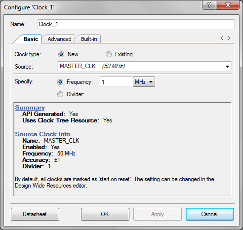
Now we need to create a suitable clock frequency; we’ll start with a 1 MHz signal, and divide it down to 1 Hz for the LED. Find the ‘Clock’ component in the System section of the Component Catalog, drag it onto the schematic, double click it, and use the following settings.
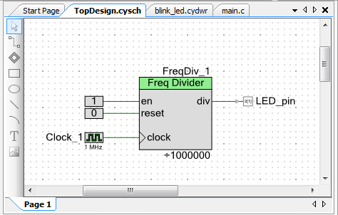
Now find the Frequency Divider in the Utility section of the Component Catalog, and drag it onto the schematic. Double-click, and set a divisor of 1000000.

All components follow the convention of having inputs on the left, outputs on the right; this part has Enable, Reset and Clock inputs. These have to be connected to something, you can’t leave inputs unconnected. Since we want the divider to be permanently enabled, and we don’t want it to be reset, we need to force Enable high, and Reset low, so find Logic High and Logic Low in the Digital Logic section of the Component Catalog, and drag one of each onto the schematic.
Now join the component pins using the wiring tool, which is the second one down in the left margin of the schematic; click on a pin, and the wire extends to the cursor; click on another pin, and they are joined. The end result should look something like:
Once joined, you can drag a component and it will remain connected; to delete a connection, click on a wire section, and press Delete.
All that remains is to get rid of our software, since everything is being done in hardware; change main.c to:
#include "project.h"
int main(void)
{
    for(;;)
    {
    }
}
Now rebuild the project, and program the device. You’ve created your first PSoC hardware project, and hopefully I’ve convinced you to carry on experimenting with these remarkable devices.
Copyright (c) Jeremy P Bentham 2019. Please credit this blog if you are using the information or software in it.
