PicoReg: real-time diagnostics for the Pi Pico using SWD

PicoReg PyQt display

The Raspberry Pi Pico CPU (RP2040) has a remarkably complex set of peripherals, and this is reflected in the very large number of control registers (1,116).

To debug a C or Python application, it can be very helpful to know the values in these registers; instead of adding ‘print’ calls, or using a heavyweight debugger, you can use a 3-wire connection between the Pico and a Raspberry Pi, and view the state of any register without modifying or disrupting the software. This magic is achieved using the Single Wire Debug (SWD) interface; it is mainly used for reprogramming the Flash memory of the Pico, but can do a lot more – it acts as a transparent window into the I/O subsystems, that is completely independent of the CPU.

This capability can be accessed using software tools such as OpenOCD, GDB, and Eclipse, but I wanted to create something much simpler, and easier to use. The end-result is PicoReg, which is a pure-Python program that runs on any Raspberry Pi. In addition to the SWD interface, it can access the standard System View Description (SVD) file, to give a description of every register in considerable detail.

The end-result is a simple-to-use software tool that gives a valuable insight into the inner workings of the Pico.

Installation

Hardware
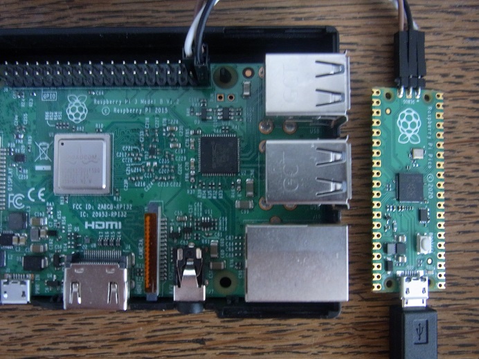
Pi -to-Pico SWD connections

Only 3 wires are needed; a ground connection, SWCLK and SWDIO.

Any I/O pins on the Pi could be used; for ease of identification, I’ve chosen BCM pin numbers 20 and 21. These should be connected to the SWCLK and SWDIO pins on the edge of the Pico; keep the wires as short as possible, ideally a 150 mm (6 inches) or less.

The pins are defined at the top of picoreg_gpio.py, so can easily be changed to any others, but you need to be sure there is no conflict with other device drivers, such as serial, SPI etc.

# Clock and data BCM pin numbers
CLK_PIN         = 20
DAT_PIN         = 21

The Pico will need to be powered as normal, for example using a 5V supply into the USB socket, or if the Pico USB interface is not connected, linking the the 5V pin on the Pi to the VSYS pin on the Pico.

Software

There are 2 Python files, and one database file:

  • picoreg_gpio.py. The low-level interface code, with a very simple command-line interface.
  • picoreg_qt.py. A PyQt application with full GUI, that uses picoreg_gpio as a low-level interface.
  • rp2040.svd. The System View Description file provided by the Raspberry Pi organisation, that describes all the peripheral registers in XML format

The GUI translates register names (such as TIMER.ALARM3) into physical addresses (such as 0x4005401c) using the SVD file; if it is missing, the GUI won’t work. The software performs best on a Pi 3 or 4; it will work on earlier devices, but is a bit slower.

The files can be found on github here; copy them to any convenient directory, then install PyQt5 on the Pi. The current version at the time of writing is 5.11.3:

sudo apt update
sudo apt install python3-pyqt5

That is all you need to do!

Running the GUI

Start the GUI from a console:

python3 picoreg_qt.py

The application will respond “Loading rp2040.vsd”, then after a short delay, will show the GUI. You may also see some warning messages from PyQt, but these are harmless.

Picoreg initial display

The controls are:

  • Core number. The Pico is a 2-core device, and this allows you to select core 0 or 1. There is no practical difference when using Picoreg to look at I/O, since the peripheral registers are common to both cores.
  • Verbose. This allows you to see the SWD messages that Picoreg is sending, and the responses obtained; useful when there are problems with the link.
  • Connect. This starts communication with the Pico, and verifies the identity of the RP2040 CPU. When the link is broken, it is necessary to re-connect before doing any register accesses.
  • Single. When connected, this button takes a single reading from the highlighted register.
  • Run. When connected, this button starts a continuous cycle of reading from the highlighted register, at 5 readings per second.

Note that this initial display is not Raspberry-Pi-specific; it will run on any PC, even under Windows. This allows you to browse the register database on any convenient machine, though the low-level I/O code is Pi-specific (using the RPI.GPIO module), so the SWD code only runs on a Pi.

The upper display is a tree structure, containing the peripherals, registers, and fields within the registers. By default it is alphabetically sorted, click on the ‘base’ header, to sort by address. The lower display shows general information, and a description of the selected register.

If the SVD database file is damaged or missing, Picoreg will report a syntax error; check that the file is in the same directory as picroreg_qy.py, and restart.

Click on ‘connect’ and if all is well, the following will be displayed.

SWD connection restart
DPIDR 0x0bc12477

The Debug Port Identification Register value shows that Picoreg connection has succeeded. The software makes 3 attempts to do this, and if unsuccessful, the most likely cause is incorrect wiring, or the Pico board not being powered up.

You can navigate around the register display using mouse (single or double-click) or keyboard, as is usual for such tree displays.

If you have a new un-programmed Pico, try navigating to the TIMER.TIMELR register, and hit ‘Run’.

Viewing timer value

You should see a rapidly-changing display of the current timer value; you can then move the cursor to other registers, whilst the data collection is still running; the register value under the cursor will be updated, while previously-accessed register values are static. There is a flashing indication in the bottom-left corner of the window to show that data collection is running.

Debugging an application

Load the following MicroPython application onto the Pico

# Simple test of O/P and ADC
from machine import Pin, Timer, ADC
led = Pin(25, Pin.OUT)
temperature = ADC(4)
timer = Timer()

def blink(timer):
    led.toggle()
    print(temperature.read_u16())

timer.init(freq=2, mode=Timer.PERIODIC, callback=blink)

The on-board LED will flash at 1 Hz, and the console will report the ADC value on the temperature channel.

You can use PicoReg to display the raw ADC value, in the ADC.RESULT register:

The state of the I/O pins is in the SIO.SPIO_IN register:


You can even see activity on the USB link, as the data pins toggle high and low:

Potential issues

Styling

This proved to be a surprising headache; it has been remarkably difficult to get consistent styling. Some of the screenshots were taken on a Pi 3 running Qt 5.11.3, remote-controlled from a PC, using SSH:

export DISPLAY=:0.0
python3 picoreg_qt.py

The others are run directly from a Pi console, and look quite different (and not as nice, in my opinion).

I’ve already used some very limited styling to customise the tree display:

TREE_STYLE    = ("QTreeView{selection-color:#FF0000;} " +
                 "QTreeView{selection-background-color:#FFEEEE;} ")

self.tree.setStyleSheet(TREE_STYLE)

However, after many hours of experimentation, I still haven’t found a way of getting a consistent appearance – feel free to tackle this problem yourself!

Errors

PicoReg uses pure-python code; on the plus side, you get the convenience of not having to install any device-drivers, but on the minus-side the SWD timing is a bit unpredictable, and can be stretched out when a higher-priority task takes control of the CPU. This is particularly noticeable when resizing or repositioning the display window; the software makes 3 attempts to re-establish connection with the Pico, but may time out and disconnect.

This behaviour is harmless, and it is only necessary to click the ‘Connect’ button to re-establish communications.

Console interface

If there are problems running the graphical interface, the low-level drivers in can be run directly from the command line:

python3 picoreg_gpio.py [options] [address]
    options: -v Verbose mode
             -r Repeated access 
    address: hexadecimal address to be monitored

The default address to be monitored is the GPIO input 0xD0000004. The low-level driver can’t access the SVD database, so the address has to be specified in hexadecimal, e.g. to display the timer value:

python3 picoreg_gpio.py -r 0x4005400c
SWD connection restart
DPIDR 0x0bc12477
0x4005400c: 0xefa1b0d0
0x4005400c: 0xefa26046
0x4005400c: 0xefa30fc8
0x4005400c: 0xefa3bf32
0x4005400c: 0xefa46ec3
..and so on, use ctrl-C to exit

How it works

The SWD link has 2 wires: a clock line, and a bi-directional data line. All transactions are initiated by the Pi, the Pico only transmits on the data line when requested. The data is sent LSB (Least Significant Bit) first.

Each message starts with an 8-bit header, and the Pico responds with a 3-bit acknowledgement; if this is OK (bit value 1, 0, 0) then a 32-bit data value is transferred (sent or received), followed by a parity bit.

As there is only one data line, the Pi has to switch its direction from transmit to receive to get the acknowledgement, and then switch back to transmit (if it is a write cycle) or allow the Pico to send 32 bits of data (if it is a read cycle).

An extra complication that isn’t emphasised in the ARM documentation, is that the active edge changes as well; the Pi sends data that is stable on the rising clock edge, but the Pico data is stable on the falling clock edge, as shown in the following oscilloscope trace. [The response from the Pico has been amplified for clarity; normally it is the same magnitude as the outgoing signal from the Pi.]

SWD header transfer; blue trace is clock (1 MHz), red trace is data

The unusual elements of this protocol make it quite tricky to implement in pure Python, and I must admit the above trace wasn’t generated by my code; it comes from OpenOCD, with an FTDI USB adaptor. The following trace is generated by my code, the frequency is a bit lower (approximately 100 kHz) and is less symmetrical.

SWD header, using Python GPIO

The asymmetric waveform isn’t a problem, but a disadvantage of the pure-Python approach is that there are occasions when the CPU is performing other tasks, and it stop driving the SWD interface.

The trace below shows a 300 microsecond pause in the middle of a transfer, and unsurprisingly the Pico doesn’t like this, and returns an error response. Occasional errors like this aren’t a problem, as they are easily handled by the retry mechanism in the PicoReg code.

SWD transfer with gap in transmission

Error handling

When there is an error, the Pico completely stops communicating over the SWD interface, and ignores all subsequent commands; it is necessary to reset the SWD interface, to re-establish communication.

The reset process is deliberately quite complex, involving the transmission of:

  • 8 all-1 bits (FF hex)
  • 16 bytes of a specific polynomial
  • 4 all-0 bits (0 hex)
  • 1 byte to activate the SW-DP interface
  • At least 50 all-1 bits

If there are any errors in the process, the Pico will not respond, which makes debugging a bit tricky. Once reset, the connection has to re-established by, transmitting the ID of the core to be accessed; the RP2040 processor has two cores, that are selected using a value of 0x01002927 or 0x11002927. When browsing the peripheral registers, it doesn’t matter which core is selected; the results will be the same.

Higher-level protocol

You might think that, having established contact with the CPU, it would be easy to read the register values, but in reality the interface has several extra levels of complication; some of these I’ve already documented in a previous project, but if you are seeking more information, you really need to read the Arm Debug Interface Architecture Specification (ADI). At the time of writing the latest version (v6.0) is available here.

Copyright (c) Jeremy P Bentham 2021. Please credit this blog if you use the information or software in it.

PC / RPi camera display using PyQt and OpenCV

OpenCV is an incredibly powerful image-processing tool, but it can be difficult to know where to start – how do you grab an image from a camera, and display it in a user-friendly GUI? This post describes such an application, that runs unmodified on a PC or Raspberry Pi, Windows or Linux, Python 2.7 or 3.x, and PyQt v4 or v5.

Installation

On Windows, the OpenCV and PyQt5 libraries can be installed using pip:

pip install numpy opencv-python PyQt5

If pip isn’t available, you should be able to run the module from the command line by invoking Python, e.g. for Python 3:

py -3 -m pip install numpy opencv-python PyQt5

Installing on a Raspberry Pi is potentially a lot more complicated; it is generally recommended to install from source, and for opencv-python, this is a bit convoluted. Fortunately there is a simpler option, if you don’t mind using versions that are a few years old, namely to load the binary image from the standard repository, e.g.

sudo apt update
sudo apt install python3-opencv python3-pyqt5 

At the time of writing, the most recent version of Raspbian Linux is ‘buster’, and that has OpenCV 3.2, which is quite usable. The previous ‘stretch’ distribution has python-opencv version 2.4, which is a bit too old: my code isn’t compatible with it.

With regard to cameras, all the USB Webcams I’ve tried have worked fine on Windows without needing to have any extra driver software installed; they also work on the Raspberry Pi, as well as the standard Pi camera with the ribbon-cable interface.

PyQt main window

Being compatible with PyQt version 4 and 5 requires some boilerplate code to handle the way some functions have been moved between libraries:

import sys, time, threading, cv2
try:
    from PyQt5.QtCore import Qt
    pyqt5 = True
except:
    pyqt5 = False
if pyqt5:
    from PyQt5.QtCore import QTimer, QPoint, pyqtSignal
    from PyQt5.QtWidgets import QApplication, QMainWindow, QTextEdit, QLabel
    from PyQt5.QtWidgets import QWidget, QAction, QVBoxLayout, QHBoxLayout
    from PyQt5.QtGui import QFont, QPainter, QImage, QTextCursor
else:
    from PyQt4.QtCore import Qt, pyqtSignal, QTimer, QPoint
    from PyQt4.QtGui import QApplication, QMainWindow, QTextEdit, QLabel
    from PyQt4.QtGui import QWidget, QAction, QVBoxLayout, QHBoxLayout
    from PyQt4.QtGui import QFont, QPainter, QImage, QTextCursor
try:
    import Queue as Queue
except:
    import queue as Queue

The main window is subclassed from PyQt, with a simple arrangement of a menu bar, video image, and text box:

class MyWindow(QMainWindow):
    text_update = pyqtSignal(str)

    # Create main window
    def __init__(self, parent=None):
        QMainWindow.__init__(self, parent)

        self.central = QWidget(self)
        self.textbox = QTextEdit(self.central)
        self.textbox.setFont(TEXT_FONT)
        self.textbox.setMinimumSize(300, 100)
        self.text_update.connect(self.append_text)
        sys.stdout = self
        print("Camera number %u" % camera_num)
        print("Image size %u x %u" % IMG_SIZE)
        if DISP_SCALE > 1:
            print("Display scale %u:1" % DISP_SCALE)

        self.vlayout = QVBoxLayout()        # Window layout
        self.displays = QHBoxLayout()
        self.disp = ImageWidget(self)    
        self.displays.addWidget(self.disp)
        self.vlayout.addLayout(self.displays)
        self.label = QLabel(self)
        self.vlayout.addWidget(self.label)
        self.vlayout.addWidget(self.textbox)
        self.central.setLayout(self.vlayout)
        self.setCentralWidget(self.central)

        self.mainMenu = self.menuBar()      # Menu bar
        exitAction = QAction('&Exit', self)
        exitAction.setShortcut('Ctrl+Q')
        exitAction.triggered.connect(self.close)
        self.fileMenu = self.mainMenu.addMenu('&File')
        self.fileMenu.addAction(exitAction)

There is a horizontal box layout called ‘displays’, that seems to be unnecessary as it only has one display widget in it. This is intentional, since much of my OpenCV experimentation requires additional displays to show the image processing in action; this can easily be done by creating more ImageWidgets, and adding them to the ‘displays’ layout.

Similarly, there is a redundant QLabel below the displays, which isn’t currently used, but is handy for displaying static text below the images.

Text display

It is convenient to redirect the ‘print’ output to the text box, rather than appearing on the Python console. This is done using the ‘text_update’ signal that was defined above:

    # Handle sys.stdout.write: update text display
    def write(self, text):
        self.text_update.emit(str(text))
    def flush(self):
        pass

    # Append to text display
    def append_text(self, text):
        cur = self.textbox.textCursor()     # Move cursor to end of text
        cur.movePosition(QTextCursor.End) 
        s = str(text)
        while s:
            head,sep,s = s.partition("\n")  # Split line at LF
            cur.insertText(head)            # Insert text at cursor
            if sep:                         # New line if LF
                cur.insertBlock()
        self.textbox.setTextCursor(cur)     # Update visible cursor

The use of a signal means that print() calls can be scattered about the code, without having to worry about which thread they’re in.

Image capture

A separate thread is used to capture the camera images, and put them in a queue to be displayed. The camera may produce images faster than they can be displayed, so it is necessary to check how many images are already in the queue; if more than 1, the new image is discarded. This prevents a buildup of unwanted images.

IMG_SIZE    = 1280,720          # 640,480 or 1280,720 or 1920,1080
CAP_API     = cv2.CAP_ANY       # or cv2.CAP_DSHOW, etc...
EXPOSURE    = 0                 # Non-zero for fixed exposure

# Grab images from the camera (separate thread)
def grab_images(cam_num, queue):
    cap = cv2.VideoCapture(cam_num-1 + CAP_API)
    cap.set(cv2.CAP_PROP_FRAME_WIDTH, IMG_SIZE[0])
    cap.set(cv2.CAP_PROP_FRAME_HEIGHT, IMG_SIZE[1])
    if EXPOSURE:
        cap.set(cv2.CAP_PROP_AUTO_EXPOSURE, 0)
        cap.set(cv2.CAP_PROP_EXPOSURE, EXPOSURE)
    else:
        cap.set(cv2.CAP_PROP_AUTO_EXPOSURE, 1)
    while capturing:
        if cap.grab():
            retval, image = cap.retrieve(0)
            if image is not None and queue.qsize() < 2:
                queue.put(image)
            else:
                time.sleep(DISP_MSEC / 1000.0)
        else:
            print("Error: can't grab camera image")
            break
    cap.release()

The choice of image size will depend on the camera used; all cameras support VGA size (640 x 480 pixels), more modern versions the high-definition standards of 720p (1280 x 720) or 1080p (1920 x 1080).

The camera number refers to the position in the list of cameras collected by the operating system; I’ve defined the first camera as number 1, but the OpenCV call defines the first as 0, so the number has to be adjusted.

The same parameter is also used to define the capture API setting; by default this is ‘any’, which usually works well; my Windows 10 system defaults to the MSMF (Microsoft Media Foundation) backend, while the Raspberry Pi defaults to Video for Linux (V4L). Sometimes you may need to force a particular API to be used, for example, I have a Logitech C270 webcam that works fine on Windows 7, but fails on Windows 10 with an ‘MSMF grab error’. Forcing the software to use the DirectShow API (using the cv2.CAP_DSHOW option) fixes the problem.

If you want to check which backend is being used, try:

print("Backend '%s'" % cap.getBackendName())

Unfortunately this only works on the later revisions of OpenCV.

Manual exposure setting can be a bit hit-and-miss, depending on the camera and API you are using; the default is automatic operation, and setting EXPOSURE non-zero (e.g. to a value of -3) generally works, however it can be difficult to set a webcam back to automatic operation: sometimes I’ve had to use another application to do this. So it is suggested that you keep auto-exposure enabled if possible.

[Supplementary note: it seems that these parameter values aren’t standardised across the backends. For example, the CAP_PROP_AUTO_EXPOSURE value in my source code is correct for the MSMF backend; a value of 1 enables automatic exposure, 0 disables it. However, the V4L backend on the Raspberry Pi uses the opposite values: automatic is 0, and manual is 1. So it looks like my code is incorrect for Linux. I haven’t yet found any detailed documentation for this, so had to fall back on reading the source code, namely the OpenCV videoio ‘cap’ files such as cap_msmf.cpp and cap_v4l.cpp.]

Image display

The camera image is displayed in a custom widget:

# Image widget
class ImageWidget(QWidget):
    def __init__(self, parent=None):
        super(ImageWidget, self).__init__(parent)
        self.image = None

    def setImage(self, image):
        self.image = image
        self.setMinimumSize(image.size())
        self.update()

    def paintEvent(self, event):
        qp = QPainter()
        qp.begin(self)
        if self.image:
            qp.drawImage(QPoint(0, 0), self.image)
        qp.end()

A timer event is used to trigger a scan of the image queue. This contains images in the camera format, which must be converted into the PyQt display format:

DISP_SCALE  = 2                 # Scaling factor for display image

    # Start image capture & display
    def start(self):
        self.timer = QTimer(self)           # Timer to trigger display
        self.timer.timeout.connect(lambda: 
                    self.show_image(image_queue, self.disp, DISP_SCALE))
        self.timer.start(DISP_MSEC)         
        self.capture_thread = threading.Thread(target=grab_images, 
                    args=(camera_num, image_queue))
        self.capture_thread.start()         # Thread to grab images

    # Fetch camera image from queue, and display it
    def show_image(self, imageq, display, scale):
        if not imageq.empty():
            image = imageq.get()
            if image is not None and len(image) > 0:
                img = cv2.cvtColor(image, cv2.COLOR_BGR2RGB)
                self.display_image(img, display, scale)

    # Display an image, reduce size if required
    def display_image(self, img, display, scale=1):
        disp_size = img.shape[1]//scale, img.shape[0]//scale
        disp_bpl = disp_size[0] * 3
        if scale > 1:
            img = cv2.resize(img, disp_size, 
                             interpolation=cv2.INTER_CUBIC)
        qimg = QImage(img.data, disp_size[0], disp_size[1], 
                      disp_bpl, IMG_FORMAT)
        display.setImage(qimg)

This demonstrates the power of OpenCV; with one function call we convert the image from BGR to RGB format, then another is used to resize the image using cubic interpolation. Finally a PyQt function is used to convert from OpenCV to PyQt format.

Running the application

Make sure you’re using the Python version that has the OpenCV and PyQt installed, e.g. for the Raspberry Pi:

python3 cam_display.py

There is an optional argument that can be used if there are multiple cameras; the default first camera is number 1.

On Linux, some USB Webcams cause a constant stream of JPEG format errors to be printed on the console, complaining about extraneous bytes in the data. There is some discussion online as to the cause of the error, and the cure seems to involve rebuilding the libraries from source; I’m keen to avoid that, so used the simple workaround of suppressing the errors by redirecting STDERR to null:

python3 cam_display.py 2> /dev/null

Fortunately this workaround is only needed with some USB cameras; the standard Raspberry Pi camera with the CSI ribbon-cable interface works fine.

Source code

Full source code is available here.

For a more significant OpenCV application, take a look at this post.

Copyright (c) Jeremy P Bentham 2019. Please credit this blog if you use the information or software in it.

PyQt serial terminal

A simple demonstration of threading in PyQt

I do a lot of work with serial comms; TeraTerm is an excellent serial terminal, but sometimes a customised application is required, for example when dealing with binary data.

The following blog describes a simple Windows & Linux serial terminal, that can be adapted to handle special protocols; it also demonstrates the creation of Python threads, and can serve as a basis for other multi-threaded applications.

pyqt_serialterm1

It won’t win any awards for style, but could come in handy next time you encounter an obscure serial protocol.

Compatibility

My code is compatible with Python 2.7 and 3.x, PyQt v4 and v5, running on Windows or Linux. This necessitates some rather clunky inclusions at the top of the file:

try:
    from PyQt4 import QtGui, QtCore
    from PyQt4.QtGui import QTextEdit, QWidget, QApplication, QVBoxLayout
except:
    from PyQt5 import QtGui, QtCore
    from PyQt5.QtWidgets import QTextEdit, QWidget, QApplication, QVBoxLayout
try:
    import Queue
except:
    import queue as Queue

There is also an issue with the different ways Python 2 and 3 handle serial data; older versions assume that the data type is an ASCII string, while in later versions it is a binary type.

This can lead to all sorts of problems (such as unwanted exceptions) so I’ve included specific functions to ensure that all outgoing data is converted from the internal representation (which could be Unicode) to a string of bytes, and incoming data is converted from the external type (data bytes or string) to a string type:

# Convert a string to bytes (for Python 3)
def str_bytes(s):
    return s.encode('latin-1')

# Convert bytes to string (if Python 3)
def bytes_str(d):
    return d if type(d) is str else "".join([chr(b) for b in d])

You’ll need to install pySerial by the usual methods (e.g. ‘pip install’).

Using threading

The key problem with serial communications is the time it takes; the slower the data rate, the longer the delay before anything happens. Without threading (or any other mitigation scheme) the User Interface (UI) will lock up after each command, waiting for the response. At best, this makes the application appear sluggish and unresponsive; at worst, it can appear to have failed, waiting for a response that never comes.

Threading allows the UI to carry on interacting with the user, while simultaneously keeping the serial link alive. Creating a new thread is really easy in Python; you just subclass QThread, and instantiate it:

class SerialThread(QtCore.QThread):
    def __init__(self, portname, baudrate):
        QtCore.QThread.__init__(self)
        self.portname, self.baudrate = portname, baudrate
...
class MyWidget(QWidget):
    ...
    self.serth = SerialThread(portname, baudrate)

I have chosen to supply the serial parameters (port name & baud rate) when the thread object is instantiated, so they are available when the thread is started; this is done by calling the start() method, which will call a run() method in the QThread class:

# In serial thread:
def run(self):
    print("Opening %s at %u baud" % (self.portname, self.baudrate))
...
# In UI thread:
    self.serth.start()

The run() method needs to keep running in a perpetual loop, but it must be possible to terminate that loop when the program exits – Python won’t do it automatically. I use a global variable, that can be set false to terminate, e.g. in pseudocode:

def run(self):
    [starting: open serial port]
    while self.running:
        [check for incoming characters]
        [check for outgoing characters]
    [finished: close serial port]

When the application is closing, it terminates the thread by setting the boolean variable false, then (very importantly) waits for the thread to finish its execution:

def closeEvent(self, event):
    self.serth.running = False
    self.serth.wait()

Transmitting

The user will be entering keystrokes in the UI thread, and it is tempting to call the serial transmit function from that thread, but this isn’t a good idea; it is better to pass the keystrokes across to the serial thread for transmission, and we need a thread-safe method of doing this. That means we can’t just use a global shared string variable; Python does a lot of behind-the-scenes processing that could lead to an unpredictable result. Instead, we’ll use a First In First Out (FIFO) queue:

# In UI thread..
txq = Queue.Queue()
...
txq.put(s)           # Add string to queue
...
# In serial thread..
if not txq.empty():
    txd = txq.get()  # Get string from queue

So the serial thread polls the transmit queue for any data, outputting it to the serial port.

Receiving

We could use the same technique for received data; the serial thread could add it to a queue that is polled by the UI thread, and somehow trigger a UI redraw when the new data arrives, but I prefer to use a signal; the data is attached to that signal, and is received by a UI function that has registered a connection. The signal has to be in a class definition, and must specify the type of data that will be attached:

class MyWidget(QWidget):
    text_update = QtCore.pyqtSignal(str)

The signal is connected to a function that will process the data:

self.text_update.connect(self.append_text)

So now the serial thread just has to generate a signal when new data is received:

self.text_update.emit(text)

This technique would be quite adequate, but I do like having the output from all my ‘print’ function calls redirected to the same window; it makes for cleaner error reporting when things go wrong, rather than having a separate console with error messages. This is done by redirecting stdout to my widget, and adding write() and flush() handlers:

class MyWidget(QWidget):
    text_update = QtCore.pyqtSignal(str)
    def __init__(self, *args): 
        ...
        self.text_update.connect(self.append_text)
        sys.stdout = self
        ...
    def write(self, text):
        self.text_update.emit(text)  
    def flush(self):
        pass
        ...
    def append_text(self, text):        
        [add text to UI display]

So now, every time I make a print() call, a signal is sent to my append_text function, where the display is updated. The use of a signal means that I can still call print() from any thread, without fear of strange cross-threading problems.

Polling in serial thread

The serial thread is just polling for incoming and outgoing characters, and if there are none, the processor will execute the ‘while’ loop really quickly. In the absence of any delays, it will consume a lot of CPU time just checking for things that don’t exist. This may appear harmless, but it is quite alarming for the user if the CPU fan starts spinning rapidly whenever your application is running, and a laptop user won’t be happy if you needlessly drain their battery by performing pointless tasks. So we need to add some harmless time-wasting to the polling loop, by frequently returning control to the operating system. This can be done by calling the ‘sleep’ function, but we still want the software to be responsive when some serial data actually arrives. A suitable compromise is to use a serial read-function with a timeout, so the software ‘blocks’ (i.e. stalls) until either some characters are received, or there is a timeout:

self.ser = serial.Serial(self.portname, self.baudrate, timeout=SER_TIMEOUT)
...
s = self.ser.read(self.ser.in_waiting or 1)

In case you are unfamiliar with the usage, the ‘or’ function returns the left-hand side if it is true (non-zero), otherwise the right-hand side. So every read attempt is at least 1 character, or more characters if they are available. If none are present, the read function waits until the timeout, so when the serial line is idle, most time will be spent waiting in the operating system.

User Interface

This has been kept as simple as possible, with just a text box as a main widget. One minor complication is that as standard, the text box (which is actually a QTextEdit control) will capture and display all keystrokes, so we need to subclass it to intercept the keys, and call a handler function that adds them to the serial transmit queue. I didn’t want to burden the text box with this functionality, so put the handler in its parent, which is the main widget:

class MyTextBox(QTextEdit):
    def __init__(self, *args): 
        QTextEdit.__init__(self, *args)

    def keyPressEvent(self, event):
        self.parent().keypress_handler(event)

The keystroke handler in the main widget gets the character from the key event, and checks for a ctrl-V ‘paste’ request; I’ve included this feature because I find it useful to cut-and-paste frequently-used serial commands from a document, rather than re-typing them every time.

# In main widget:
def keypress_handler(self, event):
    k = event.key()
    s = RETURN_CHAR if k==QtCore.Qt.Key_Return else event.text()
    if len(s)>0 and s[0]==PASTE_CHAR:
        cb = QApplication.clipboard() 
        self.serth.ser_out(cb.text())
    else:
        self.serth.ser_out(s)

Interestingly, with PyQt5 you can cut-and-paste full 8-bit data (i.e. bytes with the high bit set), but this doesn’t seem to work in PyQt4, which only accepts the usual ASCII character set.

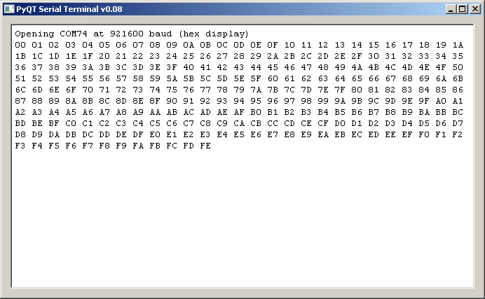
I haven’t included any menu options, you have to specify the COM port on the command-line using the -c option, and baud rate using -b. There is also a -x option to display incoming data in hexadecimal, for example:

Windows:
  python pyqt_serialterm.py -c com2 -b 9600 -x
Linux:
  python pyqt_serialterm.py -c /dev/ttyUSB0 -b 115200

On Linux, if you want non-root access to a serial port, you will generally need to add your username to the ‘dialout’ group:

sudo usermod -a -G dialout $USER

..then log out & back in.

Source code

The source code is posted here.

Copyright (c) Jeremy P Bentham 2019. Please credit this blog if you use the information or software in it.