
In a previous post, I was reading in a continuous stream of data from an ADC, but found it difficult to display; what I wanted was a real-time animated graph, similar to an oscilloscope display.
A quick search on the Internet suggested that the best way to achieve a good update speed (at least 30 updates per second) is to use the Videocore graphics processing unit (GPU), which is included on all models of the Raspberry Pi.
A high-speed display is useful for spotting noise & glitches in fast-changing data, and allows for the creation of high-resolution displays; for example, the above 10-channel display can be resized into a 1024 x 768 pixel window, whilst retaining a frame-rate around 56 FPS, which is more than adequate.
There are various ways the Videocore GPU can be programmed; unfortunately many of them have complex dependencies, making them difficult to install and use. I’m using FreeGLUT; a simple open-source OpenGL Utility Toolkit (GLUT), that can easily be installed from the latest OS distribution.
There are a very large number of OpenGL tutorials on the Web, and if you are thinking of writing your own code, I strongly recommend you take a look at them; the GPU hardware imposes unique constraints on the programming environment, so although some of the OpenGL code seems to be similar to conventional C programs, in reality there a major differences.
If you’d prefer to have a remote Web-based display, see my WebGL display project.
Shader operation

The process of programming the GPU is generally known as ‘shader programming’, as the two key components are the vertex & fragment shaders.
Put very simply, the vertex shader receives a constant stream of data (‘attributes’) describing the objects to be drawn; this is combined with some static values (‘uniforms’), under the control of the shader program, to produce a stream of pixel information (‘fragments’).
The stream of fragments are fed to the fragment shader, where they are combined with some more ‘uniforms’, under control of the fragment program, to produce the final image on the screen.
In my graphing application, the vertex attributes are a list of points to be plotted; the hardware has native support for 3-dimensional arrays, so I feed in a stream of x, y & z vertex coordinates. You may wonder why I bother with a z coordinate, since the graph is 2-dimensional, but it comes in handy to identify the individual traces. The first trace has a z-value of 1, the next is 2 and so on; this information is combined with some constant ‘uniform’ data, to control the position, scale and colour of each trace. In this way, one large block of xyz data can contain all the information for plotting several traces, without having to stop & restart the shader for each trace.
OpenGL versions
The OpenGL specification has changed a lot over the years, and with some very significant differences in the programming. To add to the complication, there are different version numbers for the OpenGL Shading Language (GLSL) and the OpenGL ES Shading Language (also known as GLSL); the latter is a somewhat reduced-functionality version designed to run on simpler hardware.
My code works on OpenGL v2.1 or OpenGLES v3.0, which is available as standard on the ‘Buster’ software distribution. In terms of hardware, the code works well on v3 and v4 boards, but is very slow on earlier versions, or the Pi Zero.
Shader programming
Normally it is necessary to write 3 separate programs; the main C program which is compiled using gcc as usual, and the two GLSL shader programs. These are written in a C-like syntax, but are compiled and linked using the OpenGL tools.
Rather than having 3 inter-dependant files, I’ve included the shader code as strings in the main C program; for example, the first 4 lines of the ES vertex shader code are:
#version 300 es
precision mediump float;
in vec3 coord3d;
flat out vec4 f_color;
These are converted to a string, so they can be included in the main program:
#define SL(s) s "\n"
char frag_shader[] =
    SL("#version 300 es")
    SL("precision mediump float;")
    SL("in vec3 coord3d;")
    SL("flat out vec4 f_color;")
    ..and so on until..
    SL("}");
An additional advantage of this approach is that defined constants can be shared between the main program and shader code. For example, the main code defines a constant with the maximum number of traces to be drawn:
#define MAX_TRACES 17
This definition can be made available in the shader code by using a macro:
// In the main program..
#define VALSTR(s) #s
#define SL_DEF(s) "#define " #s " " VALSTR(s) "\n"

// In the GLSL code string..
SL_DEF(MAX_TRACES)
The rest of the vertex shader program string looks like this:
    SL_DEF(MAX_TRACES)
    SL("uniform vec4 u_colours[MAX_TRACES];")
    SL("uniform vec2 u_scoffs[MAX_TRACES];")
    SL("vec2 scoff;")
    SL("int zint;")
    SL("bool zen;")
    SL("void main(void) {")
    SL("    zint = int(coord3d.z);")
    SL("    zen = fract(coord3d.z) > 0.0;")
    SL("    scoff = u_scoffs[zint];")
    SL("    gl_Position = vec4(coord3d.x, coord3d.y*scoff.x + scoff.y, 0, 1);\n")
    SL("    f_color = zen && zint<MAX_TRACES ? u_colours[zint] : vec4(0, 0, 0, 0);")
    SL("};");
You can see how the integer z-value is used to select the correct scale and offset (‘scoff’) value for each trace data point. The fractional part is used to enable or disable drawing (by setting the alpha value to 1 or 0), allowing the movement between one trace and another without being visible.
The fragment shader doesn’t do much; it just copies the colour value:
char frag_shader[] =
    SL("#version 300 es")
    SL("precision mediump float;")
    SL("flat in vec4 f_color;")
    SL("layout(location = 0) out vec4 fragColor;")
    SL("void main(void) {")
    SL("    fragColor = f_color;")
    SL("}");
The create_shader() function in the main program compiles this code; if there are any problems, an report is produced which goes some way towards identifying the issue, though the error reporting isn’t quite as robust and effective as one would expect from a modern C compiler.
Main program
Aside from compiling the shader code, the primary function of the main program is to prepare the list of coordnates that are to be fed into the vertex shader. The coordinates are loaded in to a single Vertex Buffer Object (VBO), so that when the shader operation begins, it can access this data at maximum speed.
The shader uses ‘normalised’ coordinates, with the bottom-left corner having the x,y value of -1, -1, and the top right 1, 1, but it is easy to use any other coordinate values, due to the strong support for matrix arithmetic.
First the background grid is drawn using individual lines. Drawing a single line in isolation requires plotting 4 points; a movement to the starting point (with alpha value zero), then setting the alpha value to 1 to start plotting, movement to the end point, then setting the alpha value back to 0. This is a bit inefficient when plotting joined-up lines, but the grid is quite simple, so this doesn’t add much to the overall plotting time.
#define ZEN(z)          ((z) + 0.1)

typedef struct {
    GLfloat x;
    GLfloat y;
    GLfloat z;
} POINT;

// Set x, y and z values for single point
void set_point(POINT *pp, float x, float y, float z)
{
    pp->x = x;
    pp->y = y;
    pp->z = z;
}

// Move, then draw line between 2 points
int move_draw_line(POINT *p, float x1, float y1, float x2, float y2, int z)
{
    set_point(p++, x1, y1, z);
    set_point(p++, x1, y1, ZEN(z));
    set_point(p++, x2, y2, ZEN(z));
    set_point(p++, x2, y2, z);
    return(4);
}
Building the software
The FreGLUT package can be installed from the latest (Buster) distro using:
sudo apt update
sudo apt install freeglut3-dev libglew-dev
There is a single C source file rpi_opengl_graph.c, that is available on Github here. The file can be compiled using:
gcc rpi_opengl_graph.c -Wall -lm -lglut -lGLEW -lGL -o rpi_opengl_graph
The top of the file has some definitions that you might like to change before compiling:
- LINE_WIDTH: width of plot line (2)
- GRID_DIVS: the number of x and y divisions in the grid (10,8)
- MAX_VALS: the maximum number of values that can be displayed (10000)
- trace_colours: the normalised colour of the grid, and the channels
- trace_scoffs: the scale & offset values for each trace (set by init_scale_offset)
The normalised colours have floating-point values of 0.0 to 1.0 for red, green and blue; I have provided a COLR macro that normalises the conventional hex colour values that are used on the Web.
There are also some command-line options:
-i <num>        Number of input channels: default 2, maximum 16
-n <num>        Number of data values per block: default 1000
-s <name>       Name of input FIFO: default /tmp/adc.fifo
-v              Verbose display for debugging
-y <num>        Maximum y-value for each trace: default 2.0

-display  <val> Standard X display selector
-geometry <val> Standard X display resolution and position
It is important to realise that the given number of data values is split between the number of channels, so if there are 1000 samples and 4 channels, each channel has 250 samples.
The data for the traces is read from a Linux FIFO (as described in a previous post on ADC streaming), in the form of comma-delimited floating-point values. Each line of text represents one set of data for all the channels, so for example there may be 1000 values from 2 channels one line, in the order ch1, ch2, ch1, ch2, etc.. The maximum number of values per line is currently defined in the code as 10,000 and the maximum number of display channels (i.e. oscilloscope traces) is currently 16, though both of these could be increased.
Running the application
The code has been tested on Pi v3 and v4 hardware; it will run on a Pi Zero or 1, but has a really low frame-rate, so isn’t really usable on that platform.
If no data is available (i.e. the Linux FIFO doesn’t exist) the application will plot some static sample traces.
./rpi_opengl_graph
# ..or to specify the display if running remotely..
./rpi_opengl_graph -display :0.0
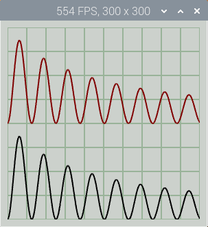
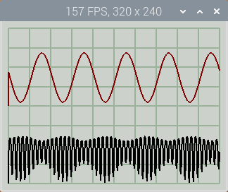
By default, 1000 points in two traces are plotted in a 300 x 300 pixel window; note the Frames Per Second (FPS) value in the title bar.
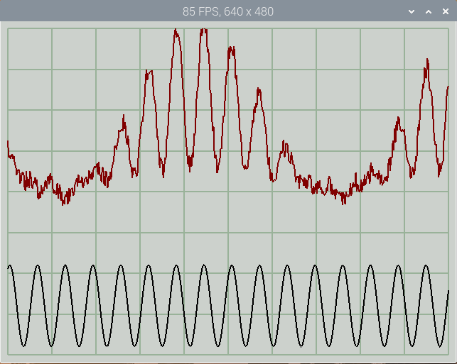
You can resize the window by specifying width & height in the standard X command-line format, e.g. for a 640 x 480 pixel window:
./rpi_opengl_graph -geometry 640x480
There is a simple console interface with 2 case-insensitive commands: ‘q’ to quit the application, and ‘p’ (or space-bar) to pause or resume the display updates.
My rpi_adc_stream application from a previous post can be used to supply the data, for example a single channel with 1000 points at 30k sample/s:
In one console:
   sudo ../dma/rpi_adc_stream -r 30000 -s /tmp/adc.fifo -i 1 -n 1000
In a second console:
  ./rpi_opengl_graph -geometry 1024x768 -i 1 -n 1000
The data source has to be run first, otherwise it won’t be detected by the graph utility.
If you don’t have access to this ADC, here is a simple Python program that generates 1000 samples in 2 channels, 50 times a second.
# Simple simulation of ADC feeding Linux FIFO

import math, time, os, signal, sys, random

fifo_name = "/tmp/adc.fifo"
ymax = 2.0
delay = 0.02
nchans = 2
npoints = 1000
running = True
fifo_fd = None

def remove(fname):
    if os.path.exists(fname):
        os.remove(fname)

def shutdown(sig=None, frame=None):
    print("\nClosing..")
    if fifo_fd:
        f.close()
    remove(fifo_name)
    sys.exit(0)

print("%u samples, %u channels, %3.0f S/s" % (npoints, nchans, npoints/delay))
remove(fifo_name)
data = npoints * [0]
n = 0;
signal.signal(signal.SIGINT, shutdown)
os.mkfifo(fifo_name)
try:
    f = open(fifo_name, "w")
except:
    running = False
while running:
    for c in range(0, npoints, nchans):
        data[c] = (math.sin((n*2 + c) / 10.0) + 1.2) * ymax / 4.0
        if nchans > 1:
            data[c+1] = (math.cos((n*2 + c) / 100.0) + 0.8) * data[c]
            data[c+1] += random.random() / 4.0
    n += 1
    s = ",".join([("%1.3f" % d) for d in data])
    try:
        f.write(s + "\n")
        f.flush()
    except:
        running = False
    sys.stdout.write('.')
    sys.stdout.flush()
    time.sleep(delay)
shutdown()
Run this script in one console, then the display application in another console, specifying a suitable window size, e.g.
./rpi_opengl_graph -geometry 640x480
The display shows two traces, one with added noise to illustrate the fast update rate.
Copyright (c) Jeremy P Bentham 2020. Please credit this blog if you use the information or software in it.
