
There are many ways to sense the position of an object, and they’re generally either expensive or low-resolution. Laser interferometers are incredibly accurate, but the complex optics & electronics make the price very high. Hand-held laser measures are quite cheap, but they use a time-of-flight measurement method which limits their resolution, as light travels at roughly 1 foot (300 mm) per nanosecond, and making sub-nanosecond measurements isn’t easy (but do check out my post on Ultra Wideband ranging, which does use lightspeed measurements). Lidar (light-based radar) is currently quite expensive, and has similar constraints. Ultrasonic methods benefit from the fact that sound waves travel at a much slower speed; they work well in constrained environments, such as measuring the height of liquid in a tank, but multipath reflections are a problem if there is more than one object in view.
Thanks to the smartphone boom, high-resolution camera modules are quite cheap, and I’ve been wondering whether they could be used to sense the position of an object to a reasonable accuracy for everyday measurements (at least 0.5 mm or 0.02 inches).
To test the idea I’ve set up 2 low-cost webcams at right-angles, to sense the X and Y position of an LED. To give a reproducible setup, I’ve engraved a baseboard with 1 cm squares, and laser-cut a LED support, so I can accurately position the LED and see the result.

The webcams are Logitech C270, that can provide an HD video resolution of 720p (i.e. 1280 x 720 pixels). For image analysis I’ll be using Python OpenCV; it has a wide range of sophisticated software tools, that allow you to experiment with some highly advanced methods, but for now I’ll only be using a few basic functions.
The techniques I’m using are equally applicable to single-camera measurements, e.g. tracking the position of the sun in the sky.
Camera input
My camera display application uses PyQt and OpenCV to display camera images, and it is strongly recommended that you start with this, to prove that your cameras will work with the OpenCV drivers. It contains code that can be re-used for this application, so is imported as a module.
Since we’re dealing with multiple cameras and displays, we need a storage class to house the data.
import sys, time, threading, cv2, numpy as np
import cam_display as camdisp

IMG_SIZE    = 1280,720          # 640,480 or 1280,720 or 1920,1080
DISP_SCALE  = 2                 # Scaling factor for display image
DISP_MSEC   = 50                # Delay between display cycles
CAP_API     = cv2.CAP_ANY       # API: CAP_ANY or CAP_DSHOW etc...

# Class to hold capture & display data for a camera
class CamCap(object):
    def __init__(self, cam_num, label, disp):
        self.cam_num, self.label, self.display = cam_num, label, disp
        self.imageq = camdisp.Queue.Queue()
        self.pos = 0
        self.cap = cv2.VideoCapture(self.cam_num-1 + CAP_API)
        self.cap.set(cv2.CAP_PROP_FRAME_WIDTH, IMG_SIZE[0])
        self.cap.set(cv2.CAP_PROP_FRAME_HEIGHT, IMG_SIZE[1])
The main window of the GUI is subclassed from cam_display, with the addition of a second display area, and storage for the camera capture data:
# Main window
class MyWindow(camdisp.MyWindow):
    def __init__(self, parent=None):
        camdisp.MyWindow.__init__(self, parent)
        self.label.setFont(LABEL_FONT)
        self.camcaps = []
        self.disp2 = camdisp.ImageWidget(self)
        self.displays.addWidget(self.disp2)
        self.capturing = True
On startup, 2 cameras are added to the window:
if __name__ == '__main__':
    app = camdisp.QApplication(sys.argv)
    win = MyWindow()
    win.camcaps.append(CamCap(2, 'x', win.disp))
    win.camcaps.append(CamCap(1, 'y', win.disp2))
    win.show()
    win.setWindowTitle(VERSION)
    win.start()
    sys.exit(app.exec_())
As with cam_display, a separate thread is used to fetch data from the cameras:
    # Grab camera images (separate thread)
    def grab_images(self):
        while self.capturing:
            for cam in self.camcaps:
                if cam.cap.grab():
                    retval, image = cam.cap.retrieve(0)
                    if image is not None and cam.imageq.qsize() < 2:
                        cam.imageq.put(image)
                    else:
                        time.sleep(DISP_MSEC / 1000.0)
                else:
                    print("Error: can't grab camera image")
                    self.capturing = False
        for cam in self.camcaps:
            cam.cap.release()
Image display
A timer event is used to fetch the image from the queue, convert it to RGB, do the image processing, and display the result.
    # Fetch & display camera images
    def show_images(self):
        for cam in self.camcaps:
            if not cam.imageq.empty():
                image = cam.imageq.get()
                if image is not None and len(image) > 0:
                    img = cv2.cvtColor(image, cv2.COLOR_BGR2RGB)
                    cam.pos = colour_detect(img)
                    self.display_image(img, cam.display, DISP_SCALE)
                    self.show_positions()

    # Show position values given by cameras
    def show_positions(self, s=""):
        for cam in self.camcaps:
            s += "%s=%-5.1f " % (cam.label, cam.pos)
        self.label.setText(s)
Image processing
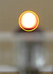
We need to measure the horizontal (left-to-right) position of the LED for each camera. If the LED is brighter than the surroundings, this isn’t difficult; first we create a mask that isolates the LED from the background, then extract the ‘contour’ of the object with the background masked off. The contour is a continuous curve that marks the boundary between the object and the background; for the illuminated LED this will approximate to a circle. To find an exact position, the contour is converted to a true circle, which is drawn in yellow, and the horizontal position of the circle centre is returned.
LOWER_DET   = np.array([240,  0,  0])       # Colour limits for detection
UPPER_DET   = np.array([255,200,200])

# Do colour detection on image
def colour_detect(img):
    mask = cv2.inRange(img, LOWER_DET, UPPER_DET)
    ctrs = cv2.findContours(mask, cv2.RETR_TREE,
                            cv2.CHAIN_APPROX_SIMPLE)[-2]
    if len(ctrs) > 0:
        (x,y),radius = cv2.minEnclosingCircle(ctrs[0])
        radius = int(radius)
        cv2.circle(img, (int(x),int(y)), radius, (255,255,0), 2)
        return x
    return 0
This code is remarkably brief, and if you’re thinking that I may have taken a few short-cuts, you’d be right:
Colour detection: I’ve specified the upper and lower RGB values that are acceptable; because this is a red LED, the red value is higher than the rest, being between 240 and 255 (the maximum is 255). I don’t want to trigger on a pure white background so I’ve set the green and blue values between 0 and 200, so a pure white (255,255,255) will be rejected. This approach is a bit too simplistic; if the LED is too bright it can saturate the sensor and appear completely white, and conversely another bright light source can cause the camera’s auto-exposure to automatically reduce the image intensity, such that the LED falls below the required level. The normal defence against this is to use manual camera exposure, which can be adjusted to your specific environment. Also it might be worth changing the RGB colourspace to HSV for image matching; I haven’t yet tried this.
Multiple contours: the findContours function returns a list of contours, and I’m always taking the first of these. In a real application, there may be several contours in the list, and it will be necessary to check them all, to find the most likely – for example, the size of the circle to see if it is within an acceptable range.
However, the measurement method does show some very positive aspects:
Complex background: as you can see from the image at the top of this blog, it works well in a normal office environment – no need for a special plain-colour background.
No focussing: most optical applications require the camera to be focussed, but in this case there is no need. I’ve deliberately chosen a target distance of approximately 4 inches (100 mm) that results in a blurred image, but OpenCV is still able to produce an accurate position indication.
Sub-pixel accuracy: with regard to measurement accuracy, the main rule for the camera is obviously “the more pixels, the better”, but also OpenCV can compute the position to within a fraction of a pixel. My application displays the position (in pixels) to one decimal place; at 4 inches (100 mm) distance, the Logitech cameras’ field of view is about 3.6 inches (90 mm), so if the position can be measured within, say, 0.2 of a pixel, this would be a resolution of 0.0006 inch (0.015 mm).
Of course these figures are purely theoretical, and the resolution will be much reduced in a real-world application, but all the same, it does suggest the technique may be capable of achieving quite good accuracy, at relatively low cost.
Single camera
With minor modifications, the code can be used in a single-camera application, e.g. tracking the position of the sun in the sky.
The code scans all the cameras in the ‘camcaps’ list, so will automatically adapt if there is only one.
The colour_detect function currently returns the horizontal position only; this can be changed to return the vertical as well. The show_positions method can be changed to display both of the returned values from the single camera.
Then you just need a wide-angle lens, and a suitable filter to stop the image sensor being overloaded. Sundial, anyone?
Source code
The ‘campos’ source code is available here, and is compatible with Windows and Linux, Python 2.7 and 3.x, PyQt v4 and v5. It imports my cam_display application, and I strongly recommended that you start by running that on its own, to check compatibility. If it fails, read the Image Capture section of that blog, which contains some pointers that might be of help.
Copyright (c) Jeremy P Bentham 2019. Please credit this blog if you use the information or software in it.
