Analog signal capture at 60 megasamples per second
This project provides a simple way of capturing data using a Pi PicoW, and displaying it wirelessly on a Web browser, as either as a logic analyser, or an oscilloscope.
The digital capture is done using the Pico I/O lines; the analogue capture uses an AD9226 parallel ADC module, that can provide up to 65 megasamples per second. The same firmware is used for both; for speed, the data is sent over the network as raw 16-bit values.
Hardware
In its simplest form, the only hardware required is a Pi PicoW module.
Minimal logic analyser circuit diagram
This can monitor 16 (or more) input lines, but it is essential that the voltage remains between 0 and 3.3V, otherwise damage will result. To accommodate wider voltages, an attenuator & comparator can be used, as in the EDLA project.
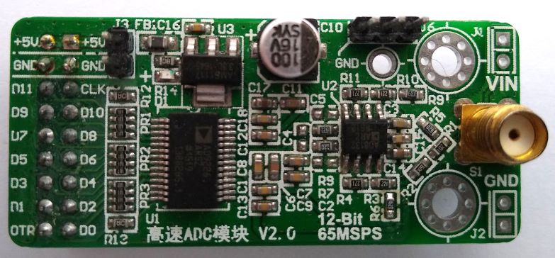
High-speed analog input uses a AD9226 ADC module, that is readily available online.
AD9226 module
It requires a 5V supply, but can be directly connected to the Pico I/O lines.
Minimal analog capture circuit diagram
Although the ADC has 12-bit resolution, only 10 bits have been used. It is possible to use all 12 bits, with minor changes to the software.
Note that some AD9226 modules have the most-significant pin marked as D0, not D11; if in doubt refer to the device datasheet, and do a continuity check between the IC pins and the I/O connections.
The ADC clock pin is connected to two I/O lines; the clock is generated on GPIO22, and read back on GPIO17. The latter is used to track the number of pulses emitted, using the pulse-counter function of the Rp2040 PWM peripheral. Any other available GPIO pins could be used instead, except that the pulse-counter function only works on odd pin numbers, so if GPIO17 is changed, it must be to an odd pin number.
When running the ADC at high speed, it is essential to keep the wiring to the Pico short (maximum 2 inches, or 5 cm) with good-quality supply & ground connections.
The analog input to the ADC module is probably 50 ohms, so can not be used with conventional oscilloscope probes. To avoid excessive loading of the input signal source, a buffer amplifier may be required.
There is a serial console output using UART1 at 115 Kbaud on GPIO pins 20 (transmit) and 21 (receive). This can be changed to use the USB link instead, by modifying the settings at the bottom of CMakeLists.txt.
Firmware
The Pico firmware is written in C; networking is implemented using the picowi WiFi driver, combined with the Mongoose TCP/IP stack; follow these links for more information. The source code is on github here.
An HTTP request is used to set the parameters and initiate a capture, e.g.
GET /status.txt?xsamp=1000&xrate=100000&cmd=1
This selects a sample count of 1000 and sample rate of 100 kHz, and the inclusion of the ‘cmd’ parameter initiates the capture.
The response is in JSON format, confirming the current state:
This confirms that 1000 samples have been captured, and are ready for transfer; if the capture is taking a long time, it will be necessary to poll the interface using a plain “GET /status.txt”, checking the ‘nsamp’ value to see when the capture is complete. If the long capture needs to be terminated, a status request with ‘cmd=0’ can be used.
The data is fetched using:
GET /status.bin
The response is a binary block with the appropriate number of 16-bit samples. For large blocks, the transfer rate is around 2 Mbyte/s.
At the time of writing, the network details are hard-coded in the firmware, so the file ‘mg_wifi.c’ needs to be edited, to change the default network name (SSID) and password.
It may also be necessary to change the network security setting, the options are:
I have experienced difficulties with the auto-switching between protocol versions, e.g. WPA2_WPA and WPA3_WPA2; if in doubt, just use the PSK versions of WPA, WPA2 or WPA3.
When the unit powers up, the on-board LED will flash rapidly, and the serial console will display something similar to the following:
WiCap v0.26
Using dynamic IP (DHCP)
Detected WiFi chip
Loaded firmware addr 0x0000, len 228914 bytes
Loaded NVRAM addr 0x7FCFC len 768 bytes
MAC address 28:CD:C1:00:C7:D1
Joining network testnet
WiFi wl0: Nov 24 2022 23:10:29 version 7.95.59 (32b4da3 CY) FWID 01-f48003fb
Joining network testnet
WiFi wl0: Nov 24 2022 23:10:29 version 7.95.59 (32b4da3 CY) FWID 01-f48003fb
Joined network
IP state: UP
IP state: REQ
IP state: READY, IP: 192.168.43.78, GW: 192.168.43.1
The dynamic IP address will depend on the settings of your network Access Point.
Once the unit has connected to the WiFi network, the LED will flash more slowly (1 Hz), and it should respond to network pings. A quick test is to enter the unit’s IP address in the browser’s address bar, and the unit ID and software version should be displayed, e.g. ‘WiCap v0.26’
Display software
In the ‘test’ directory there is a Javascript application to request & display the data in analog (oscilloscope) or digital (logic analyser) mode.
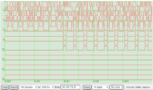
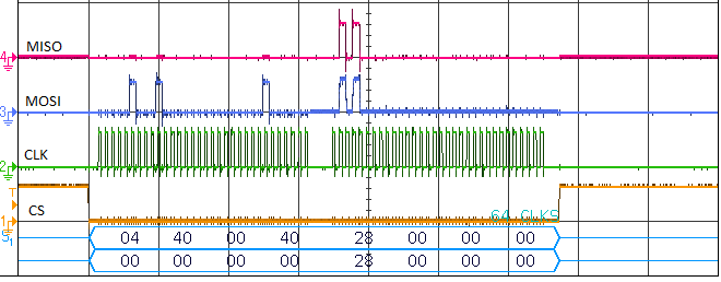
10x zoom display of 60 MS/s analog signal
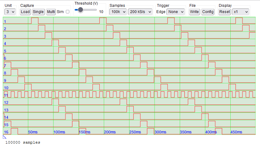
Logic analyser display
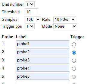
The controls are:
Single / repeat: control the data acquisition, with single or multiple captures
Sample count: number of samples required (max 100,000 for RP2040)
Sample rate: frequency of capture, up to 60 MHz for a Pico with a 120 MHz clock.
IP address: the address of the capture unit. This is printed out on the unit’s serial console at power-up.
Display: retrieve data from the unit without starting a new capture cycle.
Analogue/digital: select the number of logic analyser lines to display (8 or 16) or select the analog sensitivity (0.1, 0.2, 0.5 or 1.0 volts per division).
Zoom: Select the current zoom level; the trace can be dragged left or right to the required position.
The display code is in the ‘test’ directory on github here.
Alternative client software
An easy way to upload the data for further processing is to use WGET, e.g.
wget http://192.168.1.2/data.bin
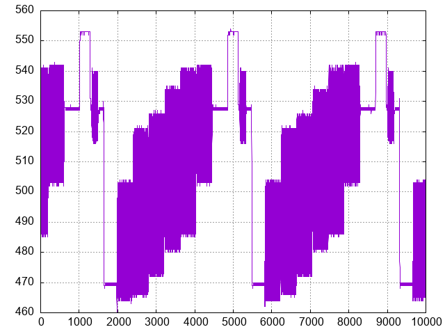
This returns a file containing 16-bit binary data. Then the data can, for example, be plotted using GNUPlot:
gnuplot -e "set term png; set output 'data.png'; set grid; unset key; plot 'data.bin' binary array=10000 format='%uword' with lines;"
GNUplot of analog data
Copyright (c) Jeremy P Bentham 2024. Please credit this blog if you use the information or software in it.
Transmission Control Protocol (TCP) is an important next step in the PioWi protocol stack; it opens the way to various network applications, such as the ubiquitous Web server.
In this post I’ll be introducing a fast Web server, that can be used for intensive data-transmission duties; in the next post it’ll be used to implement a Web camera with still- and video-image capabilities.
TCP
At first sight, TCP may look quite simple to implement; it adds reliability to the network transmissions by establishing a ‘connection’ between 2 systems, with each side tracking the other’s transmissions, and acknowledging receipt. However, there are various subtleties to the TCP protocol that make it very challenging to implement, namely:
Out-of-order arrival. Since there is no fixed path for the data blocks to move across the network, a newer block may arrive after an older one.
Data flow. A unit that sends data must regulate its flow so as to not overwhelm the receiver.
Disorderly shutdown. When the data transfer is complete, sender and receiver will attempt to shut down the connection in an orderly fashion, but sometimes this will fail, leaving a connection half-open.
Buffering. The data sender won’t know if its data has been received until an acknowledgement is received from the receiver, so it must buffer the data just in case it has to be resent.
Symmetry. Although one system ( the ‘client’) initiates communication with another (the ‘server’), once the connection is established it is completely symmetrical, with either side being able to send & receive the data, or terminate the connection.
Multiple connections. Servers are usually required to handle multiple simultaneous connections, from multiple clients.
It is well worth reading the TCP specification RFC9293; implementing a full-scale TCP stack is a complex task, so the initial focus of this post will be on a server that primarily sends data – it receives requests from clients, but is optimised for the sending of bulk data from server to client.
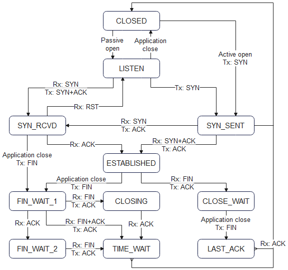
State machine
TCP state machine
The behaviour of the TCP stack is controlled by a sate machine, that processes open/close/acknowledgement signals from the remote system, and open/close signals from a higher-level application, and decides what to do next. The signals from the remote system are in the form of binary flags, most notably:
SYN: open a connection (synchronise)
ACK: acknowledge a transmission
FIN: close a connection (finish)
RST: reject a transmission (reset)
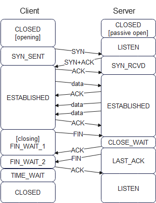
Since the connection is symmetrical, both sides have to receive a SYN to make the connection, and a FIN to close that connection. Here is a sample transaction, showing how a Web client and server might transfer a small Web page:
Sample TCP client-server transaction
The server has a permanently-open port (‘passive’ open) that is ready to accept incoming connection requests. The client application sets up the connection by sending a SYN to the server, which responds with SYN + ACK, then the client sends an ACK to confirm. Both sides now consider the connection to be ‘established’, and either side can start sending data. In the case of a Web browser, the client sends an HTTP-format request for a Web page; the details of that request will be explained later.
After the server acknowledges the request, it sends 2 data blocks as a response, which the client acknowledges using a single ACK. In this example I’ve then shown the client closing the connection by sending a FIN, which is acknowledged, then confirmed by the server sending a FIN, however in many cases there will be a more sizeable exchange of data, and the connection might be kept open for further requests and responses, to avoid the (very significant) overhead of opening and closing the connection.
TCP sequence number and window size
Both sides of the TCP connection need to keep track of the data sent & received; this is done with a ‘sequence number’, that essentially points to the current starting position of the data within a virtual data buffer, with 3 extra complications:
The SYN and FIN markers each count as 1 extra data byte.
The first transmission doesn’t have a sequence number of zero; a pseudo-random value is used, to reduce the likelihood of the current data blocks being confused with blocks that might be left over from a previous transaction.
The number is 32 bits wide. and wraps around when the maximum value is exceeded.
To avoid congestion, there must some way for a unit to signal how much buffer space it has left; this is done by the ‘window size’ parameter in the TCP message. This value isn’t necessarily a reflection of the actual space available, as there is a danger that a small value will cause a lot of small data blocks to be generated (which is very inefficient), rather than waiting for a good-sized space to be available.
Message format
The protocol header has source & destination port numbers (similar to UDP), also the sequence & acknowledgement numbers and window size, that are needed for error handling and flow control. The flags are a bit-field containing SYN, ACK, FIN, RST and other indications.
/* ***** TCP (Transmission Control Protocol) header ***** */
typedef struct tcph
{
    WORD  sport,            /* Source port */
          dport;            /* Destination port */
    DWORD seq,              /* Sequence number */
          ack;              /* Ack number */
    BYTE  hlen,             /* TCP header len (num of bytes << 2) */
          flags;            /* Option flags */
    WORD  window,           /* Flow control credit (num of bytes) */
          check,            /* Checksum */
          urgent;           /* Urgent data pointer */
} TCPHDR;

#define TCP_DATA_OFFSET (sizeof(ETHERHDR) + sizeof(IPHDR) + sizeof(TCPHDR))

#define TCP_FIN     0x01    /* Option flags: no more data */
#define TCP_SYN     0x02    /*           sync sequence nums */
#define TCP_RST     0x04    /*           reset connection */
#define TCP_PUSH    0x08    /*           push buffered data */
#define TCP_ACK     0x10    /*           acknowledgement */
#define TCP_URGE    0x20    /*           urgent */
The checksum is similar to UDP in that it includes a ‘pseudo-header’ with source & destination IP addresses.
/* ***** Pseudo-header for UDP or TCP checksum calculation ***** */
/* The integers must be in hi-lo byte order for checksum */
typedef struct              /* Pseudo-header... */
{
    IPADDR sip,             /* Source IP address */
          dip;              /* Destination IP address */
    BYTE  z,                /* Zero */
          pcol;             /* Protocol byte */
    WORD  len;              /* UDP length field */
} PHDR;
HTTP
TCP can be used to carry a wide variety of higher-level protocols, but a frequent choice is Hypertext Transfer Protocol (HTTP), that is used by a Web browser to request data from a Web server.
An HTTP request consists of:
A request line, specifying the method to be used, the resource to be accessed, and the HTTP version number. A query string may optionally be appended to the resource name, to provide additional requirements.
Optional HTTP headers, or header fields, specifying additional parameters
A blank line, marking the end of the header
A message body, if needed
The server responds with:
A status line, with a status code and reason phrase, indicating if the resource is available.
HTTP headers, or header fields, giving information about the resource, and the server that is providing it.
Web browsers have a create tendency to store (‘cache’) and re-use Web pages, which is a major problem if we are trying to display ‘live’ data, so the NOCACHE header can be used to tell the browser not to cache the resource data.
A browser can handle a wide range of data formats, but only if it is informed which format has been used. The CONTENT headers clarify this, and are essential for displaying the data correctly.
A feature of modern Web browsers is that they block ‘cross-site scripting’ by default. This means that the browser can’t insert data from one server, whilst displaying a page from another. This is very important when dealing with high-security applications such as banking, to prevent a rogue site from impersonating a legitimate site by displaying portions of its pages. It also forces all the pages and data to be hosted on a single Web server, which can be a nuisance for embedded systems with limited capabilities; it is better to host the static Web pages on another site, so the embedded system just has to provide the sensor data to be displayed on those pages. The ORIGIN_ANY header enables this, by allowing the data to be used by any other Web site.
The MULTIPART definition is useful for defining a video stream, that consists of a sequence of still images. The video server I’m creating uses Motion JPEG (MJPEG) which is just a stream of JPEG images, so the browser needs an indication as to where one image ends, and the next begins. So MULTIPART specifies a (hopefully unique) marker that can be sent after each frame as a delimiter, that triggers the browser to display the last-received frame, and prepare to receive a new one. The end-result is that the still images are displayed as a continuous stream, emulating a conventional video file, albeit with a larger file-size, due to the absence of inter-frame compression.
Web server API
Programming a Web server in C can get quite complicated, especially when we’re not running a multi-tasking operating system. The usual model is for each connection to ‘block’ (i.e. stall) until data is available, but that isn’t feasible in a single-tasking system.
So instead I’ve created an event-oriented system, where a callback function is registered for each Web page:
These handler functions are only called if the relevant Web page is requested, so they don’t consume any resources until that happens.
If the page just has some simple static text, that is loaded into a buffer, and a socket closure is requested:
// Handler for test page
int web_test_handler(int sock, char *req, int oset)
{
    static int count = 1;
    int n = 0;

    if (req)
    {
        printf("TCP socket %d Rx %s\n", sock, req);
        sprintf(temps, "<html><pre>Test %u</pre></html>", count++);
        n = web_resp_add_str(sock,
            HTTP_200_OK HTTP_SERVER HTTP_NOCACHE HTTP_CONNECTION_CLOSE
            HTTP_CONTENT_HTML HTTP_HEADER_END) +
            web_resp_add_str(sock, temps);
        tcp_sock_close(sock);
    }
    return (n);
}
The ‘req’ parameter is the browser text requesting the resource, which can be parsed to extract the parameter values from a query string.
The ‘oset’ parameter is used when the Web response doesn’t fit into a single response message. It tracks the current position within the data buffer, which normally is equal to the total amount of data so far, but under error conditions, it will step back to an earlier value. A typical usage is to use the value as an index into a data buffer, not forgetting the HTTP response header, which is at the start of the first data block. The following code returns a stream of blocks for each image, until all the image has been sent, which triggers a new multipart header and image capture:
#define TCP_MAXDATA   1400

// Handler for single camera image
int web_cam_handler(int sock, char *req, int oset)
{
    int n = 0, diff;
    static int startime = 0, hlen = 0, dlen = 0;

    if (req)
    {
        hlen = n = web_resp_add_str(sock,
            HTTP_200_OK HTTP_SERVER HTTP_NOCACHE HTTP_CONNECTION_CLOSE
            HTTP_CONTENT_JPEG HTTP_HEADER_END);
        dlen = cam_capture_single();
        n += web_resp_add_data(sock, cam_data, TCP_MAXDATA - n);
    }
    else
    {
        n = MIN(TCP_MAXDATA, dlen + hlen - oset);
        if (n > 0)
            web_resp_add_data(sock, &cam_data[oset - hlen], n);
        else
            tcp_sock_close(sock);
    }
    return (n);
}
Test Web server
web_server.c is a test program to demonstrates the ability of a Web server to return large amounts of data at high speed (over 20 megabits per second). It transfers dummy binary data in text format (base-64) or in raw binary.
It has the following Web pages:
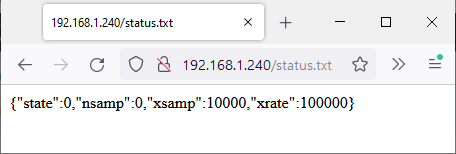
status.txt
This is a simple status message with dummy parameters in JSON format, e.g.
This demonstrates how dynamic numeric values could be propagated from server to client.
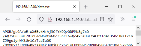
data.txt
This demonstrates the transfer of a large binary block using base-64 encoding, which converts every 3 bytes into 4 ASCII characters. This technique is used when we want to avoid the complication of handling raw binary.
The microsecond timer on the Pico is used to record the start & ending times of the data transfer, so as to print the data rate on the Pico serial console.
data.bin
This transfers blocks of data in pure binary format, and the throughput rate is reported.
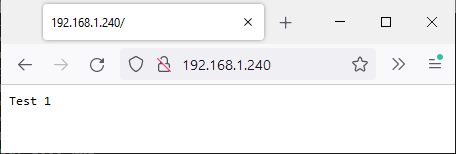
default
The default Web page just returns the string ‘test’ and a number that increments with every access, to show that the page isn’t being cached.
Running the Web server
By default, the server will try to connect to the default Wifi network (‘testnet’) so you will probably need to change the definition at the top of the server code to match your network name and password.
If you are using the Pi development environment described in the introduction, then compiling and running the Web server requires just 2 steps:
make web_server
./prog web_server
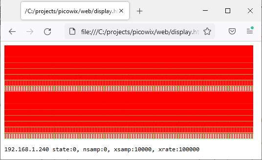
When it boots, the server will report its IP address on the serial console, e.g. 192. 168.1.240. Enter that address into a Web browser, to see the (really simple) default page, with a number that increments every time you re-fetch the page:
To see the raw JSON-format status page, access status.txt:
You can also view the start of the base-64 format data, though this isn’t very enlightening:
To demonstrate how the status & data information can be decoded and displayed, I have included an HTML file web/display.html, which is an adaptation of my ‘EDLA’ logic analyser code.
Before loading this file, you need to edit the IP address at the top to match your Pico server, and also select binary or base-64 mode for the transfer:
const remip = "192.168.1.240", bin_mode = true;
The resulting display shows a logic-analyser-style display of the incoming data, with the text from the status file underneath. The graphic is much too dense to be any use, but it does show how a large block of data can be transferred and displayed with remarkable speed.
In part 5, we joined a WiFi network, and used ‘ping’ to contact another unit on that network, but this was achieved by setting the IP address manually, which is generally known as using a ‘static’ IP.
The alternative is to use a ‘dynamic’ IP, that a central server (such as the WiFi Access Point) allocates from a pool of available addresses, using Dynamic Host Configuration Protocol (DHCP); this also provides other information such as a netmask & router address, to allow our unit to communicate with the wider Internet.
IP addresses and routing
So far, I’ve just said that an IP address consists of 4 bytes, that are usually expressed as decimal values with dotted notation, e.g. 192.168.1.2, but there is some extra complication.
Firstly it is important to note I’m using version 4 of the protocol (IPv4); there is a newer version (IPv6) with a much wider address range, but the older version is sufficient for our purposes, and easier to implement.
Next it is important to distinguish between a public and private IP address.
Public: an address that is accessible from the Internet, generally assigned by an Internet Service Provider (ISP)
Private: an address used locally within an organisation, that is not unique; generally assigned from the blocks 192.168.x.x, 172.16.x.x or 10.x.x.x
The address we’ll be getting from the DHCP server is probably private; if we are accessing the Internet, there will be one or more network devices (‘routers’) that perform public-to-private translation, and also security functions (‘firewalls’) to block malicious data.
If our unit has an IP address it wishes to contact, how does it know what to do? It just has to determine if the target address is local or remote by applying a netmask. For example if our unit is given the address 192.168.1.1 with netmask 255.255.255.0, then a logical AND of the two values means that our local network (known as a ‘subnet’) is 192.168.1. If the unit we’re contacting is on that subnet (i.e. the address begins with 192.168.1) then we just send out a local ARP request to convert their IP address into a MAC address, and start communicating.
If the target address isn’t on the same subnet (e.g. 192.168.2.1, 11.22.33.44, or anything else) then our unit contacts a router (using the address given in the DHCP response) and relies on the router to forward the data appropriately.
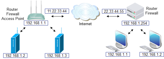
In the diagram above, there are networks with public addresses 11.22.33.44 and 22.33.44.55, and they both have private addresses in 192.168.1.x subnetworks; the job of the router is to move the data between these subnetworks by performing Network Address Translation (NAT) between them.
If unit 192.168.1.3 wants to contact 22.33.44.55 it will check the netmask, and because the target isn’t on the same subnetwork, the data will be sent to the router 192.168.1.1, which will forward it over the Internet.
If 192.168.1.3 wants to contact 192.168.1.2, ANDing with the netmask will show that they are both on the same subnet, so the data will be sent directly, bypassing using the router.
However, if 192.168.1.3 wants to send the data to 192.168.1.1 on the remote network, how does the router know what to do? The simple answer is “it doesn’t”, as addresses on the 192.168.1.x subnet aren’t unique, and there will be thousands (or millions!) of units with that same address around the world. Also the netmask clearly indicates that 192.168.1.1 must be on the same subnet as 192.168.1.3, so the data will be sent locally to 192.168.1.1, whether it exists or not; if it doesn’t exist, that’ll be flagged up by the ARP request failing.
There are various workarounds for this ‘NAT traversal’ problem, for example 192.168.1.3 sends the data to the router 22.33.44.55, which is configured to copy incoming data to 192.168.1.1, but there are major security risks associated with opening up a system to unfiltered Internet traffic, so for the purposes of this blog, I’m assuming that our unit will only be communicating with other units on the same subnetwork, or publicly-available systems on the Internet.
The above example assumes there is a single router for all outgoing traffic, and this is generally the case on a WiFi network, where the Access Point also acts as a router. However, on more complex networks there can be multiple routers to provide alternative routes to other networks or the Internet.
Client and server
The most common model for communication between two systems is client-server. The server runs continuously, waiting for a client to get in contact. The client uses a specific communications format (a ‘protocol’) to establish a link (‘connection’) to the server. The connection persists for as long as is needed to exchange the data, then it is closed by both sides.
Simpler protocols can dispense with the connection, but still retain the client-server model; for example, to fetch the time with Network Time Protocol (NTP) you just send a single message to a time server, and get a single message back with the time. This ‘connectionless’ approach means that a single ‘stateless’ server can handle very large numbers of clients, since it doesn’t have to track the state of its clients; an incoming request has all the information needed to send the response.
UDP message format
So there are two distinct ways for a client to communicate with a server; one creates a persistent connection, with both sides tracking the flow of data, and re-sending any data that is lost in transit: this is Transmission Control Protocol (TCP). The other way is User Datagram Protocol (UDP), which has no such tracking, or error correction; just send a block of data and hope it arrives.
This uncertainty means that, if faced with a choice, many programmers reject UDP as being too unreliable, however it does have a very important place in the suite of TCP/IP protocols, not least because it is used for DHCP.
A DHCP transmission consists of the following:
Ethernet header
IP header
UDP header
DHCP header
DHCP option data
We’ve already used the Ethernet and IP headers when sending an ICMP (ping) message, this time we’re stacking on a UDP header.
/* ***** UDP (User Datagram Protocol) header ***** */
typedef struct udph
{
    WORD  sport,            /* Source port */
          dport,            /* Destination port */
          len,              /* Length of datagram + this header */
          check;            /* Checksum of data, header + pseudoheader */
} UDPHDR;
There is a 16-bit length, which shows the total length of the header plus any data that follows, and a 16-bit checksum, which is calculated in an unusual manner; it incorporates the UDP header, parts of the IP header, and all the data that follows. The way this is calculated is to create a pseudo-header containing the relevant IP parts:
/* ***** Pseudo-header for UDP or TCP checksum calculation ***** */
/* The integers must be in hi-lo byte order for checksum */
typedef struct              /* Pseudo-header... */
{
    IPADDR sip,             /* Source IP address */
          dip;              /* Destination IP address */
    BYTE  z,                /* Zero */
          pcol;             /* Protocol byte */
    WORD  len;              /* UDP length field */
} PHDR;
So the UDP code has to prepare two headers, though the pseudo-header is only used for checksum calculation, and can be discarded after that is done.
Another notable feature of the UDP header is the source & destination port numbers, and these deserve some explanation.
A port number can identify a specific service on a server; for example port 80 identifies an HTTP web server, and 67 is a DHCP server. These are ‘well-known’ port numbers and are in the range 0 to 1023. Ports numbered 1024 to 49151 are also used for specific server functionality that isn’t part of the original set, so are known as ‘registered’. The remaining numbers 49152 to 65535 are ‘dynamic’ ports, that are used temporarily by client applications.
When a client wishes to communicate with a server, it will obtain a dynamic port from its operating system, and use that port for the duration of a transaction, releasing it when the transaction is complete. In contrast, a server will generally monopolise a well-known or registered port on a permanent basis, though some servers additionally open up a dynamic port on a short-term basis to handle a specific interaction with the client, such as a file transfer.
Unusually, the DHCP server & client are both assigned well-known numbers, namely UDP 67 and 68. You may see these identified as BOOTP ports, since DHCP is based on the older BOOTP protocol, with some additions.
DHCP message format
DHCP is a 4-step process:
Discover: the unit broadcasts a request asking for network parameters, such as an IP address it can use, also a router address, and subnet mask.
Offer: the server responds with some proposed values, that the unit can accept or reject.
Request: the unit signifies its acceptance of the proposed values
ACK: the server acknowledges the request, indicating that the parameters have been assigned to the unit.
Once the parameters have been assigned, the server will generally attempt to keep them unchanged, such that every time the unit boots, it will get the same IP address. However, this is not guaranteed, and a busy server with a lot of temporary clients will be forced to re-use addresses from units that haven’t been active for a while.
The message format is based on the older protocol BOOTP:
typedef struct {
  	BYTE  opcode;   			/* Message opcode/type. */
	BYTE  htype;				/* Hardware addr type (net/if_types.h). */
	BYTE  hlen;					/* Hardware addr length. */
	BYTE  hops;					/* Number of relay agent hops from client. */
	DWORD trans;				/* Transaction ID. */
	WORD secs;					/* Seconds since client started looking. */
	WORD flags;					/* Flag bits. */
	IPADDR ciaddr,				/* Client IP address (if already in use). */
           yiaddr,				/* Client IP address. */
           siaddr,				/* Server IP address */
           giaddr;				/* Relay agent IP address. */
	BYTE chaddr [16];		    /* Client hardware address. */
	char sname[SNAME_LEN];	    /* Server name. */
	char bname[BOOTF_LEN];		/* Boot filename. */
	BYTE cookie[DHCP_COOKIE_LEN];   /* Magic cookie */
} DHCPHDR;
When making the initial discovery request, many of these values are unused; the ‘cookie’ is filled in with a specific 4-byte value (99, 130, 83, 99) that signal this is a DHCP request, not BOOTP. Then there is a data field with ‘option’ values; each entry has one byte indicating the option type, one byte indicating data length, and that number of data bytes. The options I use in the discovery request are a byte value of 1, indicating it is a discovery message, and 4 parameter values, indicating what should be provided by the server (1 for subnet mask, 3 for router address, 6 for nameserver address and 15 for network name).
The resulting offer from the server probably includes much more than we asked for; this is what my server returns:
    Option: (53) DHCP Message Type (Offer)
    Option: (54) DHCP Server Identifier (192.168.1.254)
    Option: (51) IP Address Lease Time (7 days)
    Option: (58) Renewal Time Value (3 days, 12 hours)
    Option: (59) Rebinding Time Value (6 days, 3 hours)
    Option: (1) Subnet Mask (255.255.255.0)
    Option: (28) Broadcast Address (192.168.1.255)
    Option: (15) Domain Name ("home")
    Option: (6) Domain Name Server (192.168.1.254)
    Option: (3) Router (192.168.1.254)
    Option: (255) End
You’ll see that the Access Point 192.168.1.254 is acting as a router and nameserver; we’ll be looking at the Domain Name System (DNS) in the next part of this blog.
If the unit wants to accept these proposed settings, it must send a request containing the proposed IP address. This can have the same format as the discovery, with a byte value of 3, indicating it is a request message, and a the 4-byte address value:
// DHCP request options
DHCP_MSG_OPTS dhcp_req_opts =
   {53, 1, 3,               // Msg len 1 type 3: request
    50, 4, {0, 0, 0, 0},    // Address len 4 (copied from offer)
    255};                   // End
Assuming all is OK, the ACK response from the server will be similar to the offer, maybe with more values added (such as vendor-specific information), so an important part of the receiver code is the scanning of the parameters to find the values that are needed.
State machine
If we were in a multi-tasking environment, the DHCP process might basically consist of a sequence of 4 function calls, each function stopping (‘blocking’) until it is complete:
Since we don’t currently have multi-tasking, we can’t adopt this approach, as it would block any other code from running, and in the event of an error, one of these functions might stall indefinitely. Instead, we have to adopt a ‘polled’ approach, where we keep on re-visiting this process to see what (if anything) has changed. The key to this is to have a single ‘state’ variable that reflects what has happened, e.g. it has a value of 1 when we have sent the discovery, 2 when we have received an offer, and so on.
The polling of the DHCP state also incorporates a timeout, that is triggered in the event of an error; with a simple 4-step protocol like this, we can just restart the process from the beginning, rather than trying to work out where the error occurred.
Example program
There is one example program dhcp.c that fetches IP addresses and netmask from a DHCP server, and prints the result:
This allows you to see the message-passing; it isn’t unusual to receive duplicate messages, and in the DHCP OFFER above. The ARP display is also enabled so you can see the router using ARP to check the newly-assigned address.
It will be necessary to change the default SSID and PASSWD to match your network; for details on how to build & load the application, see the introduction.
In part 4, the wireless chip was connected to a WiFi network, so it can now send & receive data on that network, but we still have to encode the data for transmission, and decode it for reception.
We’re using a ‘full MAC’ chip, so all the low-level WiFi interfacing is handled within the chip. When transmitting, it encrypts our data, and adds the necessary 802.11 headers so that it will accepted by the network access point; when receiving, the headers are stripped off and the data is decrypted before being passed over to the Pico CPU.
This doesn’t just make our encoding & decoding tasks easier, it also ensures that the transmissions fully conform to the (exceedingly complex) 802.11 rules; if your interest is in creating non-standard wireless transmissions, then I’m afraid this project will be of no help.
TCP/IP
The suite of protocols used for data transmission over the Internet are generally known as Transmission Control Protocol / Internet Protocol, or TCP/IP. We’ll only be using a small subset of these protocols, and the initial task is just to handle Address Resolution Protocol (ARP) and Internet Control Message Protocol (ICMP). This will allow us to send & receive diagnostic ‘ping’ messages, and do some simple benchmarks by communicating with another system.
TCP/IP uses a three-tier addressing system; at the highest level, there are names with dotted notation, such as iosoft.blog or http://www.google.com. To access the computer at this address, two further steps are required:
a Domain Name System (DNS) database lookup is used to convert the name into an Internet Protocol (IP) address, which has 4 numeric values in dotted notation, for example 192.168.5.1
an Address Resolution Protocol (ARP) message is sent out on the network, with a request to convert the remote unit’s IP address into a Media Access and Control (MAC) address, which has 6 bytes, that are normally printed with a colon separator, e.g. 28:CD:C1:00:12:34
The first of these will be tackled in the next part of this project; for now, I’m assuming that the unit has obtained an IP address from somewhere, and knows the IP address of another unit it wishes to communicate with, for example the WiFi access point.
Address Resolution Protocol (ARP)
This is probably the simplest of all TCP/IP protocols; the unit broadcasts a request in a specific format, giving the IP address it wants to contact, and if any unit on the same ‘subnet’ has that address, then it will respond with its 6-byte MAC address. That is used for outgoing messages, but for incoming messages our unit must listen out for ARP broadcasts, and if a request matches its IP address, it should respond with the MAC address.
The ARP message format can be encapsulated within a C structure:
typedef unsigned char  BYTE;
typedef unsigned short WORD;
typedef unsigned int   DWORD;
typedef BYTE MACADDR[MACLEN];
typedef unsigned int IPADDR;

/* ***** ARP (Address Resolution Protocol) packet ***** */
typedef struct
{
    WORD hrd,           /* Hardware type */
         pro;           /* Protocol type */
    BYTE  hln,          /* Len of h/ware addr (6) */
          pln;          /* Len of IP addr (4) */
    WORD op;            /* ARP opcode */
    MACADDR  smac;      /* Source MAC addr */
    IPADDR   sip;       /* Source IP addr */
    MACADDR  dmac;      /* Destination MAC addr */
    IPADDR   dip;       /* Destination IP addr */
} ARPKT;
This is the first of many C structures for TCP/IP, and I’ve chosen to define 8, 16 and 32-bit values as BYTE, WORD and DWORD for clarity.
To broadcast this message, we need to add on Ethernet header, giving a source MAC address (the MAC address of our unit, as reported by the WiFi chip) the destination MAC address (broadcast, which is all-ones, i.e. FF:FF:FF:FF:FF:FF) and a protocol ID, which indicates that we’re sending an ARP packet.
/* Ethernet (DIX) header */
typedef struct {
    MACADDR dest;               /* Destination MAC address */
    MACADDR srce;               /* Source MAC address */
    WORD    ptype;              /* Protocol type or length */
} ETHERHDR;
#define PCOL_ARP    0x0806      /* Protocol type: ARP */
#define PCOL_IP     0x0800      /*                IP */
There are a lot of similarities between the higher level of wired (Ethernet) and wireless (802.11) protocols, so it makes sense that both use the same network address structure.
Creating an ARP request is really just a fill-in-the-blanks exercise:
All network data is in big-endian format (most-significant byte first), but the RP2040 processor is little-endian, so the 16-bit values need to be byte-swapped.
To transmit the message, all that is needed is to add on the SDPCM layer for the WiFi chip, and copy it into an outgoing message buffer:
// Transmit an ARP frame
int ip_tx_arp(MACADDR mac, IPADDR addr, WORD op)
{
    int n = ip_make_arp(txbuff, mac, addr, op);

    return(ip_tx_eth(txbuff, n));
 }

// Send transmit data
int ip_tx_eth(BYTE *buff, int len)
{
    return(event_net_tx(buff, len));
}
// Transmit network data
int event_net_tx(void *data, int len)
{
    TX_MSG *txp = &tx_msg;
    int txlen = sizeof(SDPCM_HDR)+2+sizeof(BDC_HDR)+len;

    display(DISP_DATA, "Tx_DATA len %d\n", len);
    disp_bytes(DISP_DATA, data, len);
    display(DISP_DATA, "\n");
    txp->sdpcm.len = txlen;
    txp->sdpcm.notlen = ~txp->sdpcm.len;
    txp->sdpcm.seq = sd_tx_seq++;
    memcpy(txp->data, data, len);
    if (!wifi_reg_val_wait(10, SD_FUNC_BUS, SPI_STATUS_REG,
            SPI_STATUS_F2_RX_READY, SPI_STATUS_F2_RX_READY, 4))
        return(0);
    return(wifi_data_write(SD_FUNC_RAD, 0, (uint8_t *)txp, (txlen+3)&~3));
}
The transmit data length is rounded up to the nearest 4 bytes, as the WiFi DMA controller only works handles complete 4-byte words.
ARP reception
An incoming message will arrive as an ‘event’ from the WiFi chip, and a handler function first checks that it is valid:
If the incoming message is an ARP request, then the receiver function transmits an appropriate response. If it is a response, the resulting MAC address is saved, for use in future transmissions:
// Receive incoming ARP data
int ip_rx_arp(BYTE *data, int dlen)
{
    ETHERHDR *ehp=(ETHERHDR *)data;
    ARPKT *arp = (ARPKT *)&data[sizeof(ETHERHDR)];
    WORD op = htons(arp->op);

    if (arp->dip == my_ip)
    {
        if (op == ARPREQ)
            ip_tx_arp(ehp->srce, arp->sip, ARPRESP);
        else if (op == ARPRESP)
            ip_save_arp(arp->smac, arp->sip);
        return(1);
    }
    return(0);
}
Ping
Ping request & response format
Having obtained the 6-byte MAC address of a unit we wish to communicate with, what can we send to it? The obvious choice is a diagnostic ‘ping’, that echoes back the data we send, and measures the round-trip time.
Ping uses the Internet Control Message Protocol (ICMP), with an IP header for the address information:
/* ***** ICMP (Internet Control Message Protocol) header ***** */
typedef struct
{
    BYTE  type,         /* Message type */
          code;         /* Message code */
    WORD  check,        /* Checksum */
          ident,        /* Identifier */
          seq;          /* Sequence number */
} ICMPHDR;
#define ICREQ           8   /* Message type: echo request */
#define ICREP           0   /*               echo reply */

/* ***** IP (Internet Protocol) header ***** */
typedef struct
{
    BYTE   vhl,         /* Version and header len */
           service;     /* Quality of IP service */
    WORD   len,         /* Total len of IP datagram */
           ident,       /* Identification value */
           frags;       /* Flags & fragment offset */
    BYTE   ttl,         /* Time to live */
           pcol;        /* Protocol used in data area */
    WORD   check;       /* Header checksum */
    IPADDR sip,         /* IP source addr */
           dip;         /* IP dest addr */
} IPHDR;
#define PICMP   1           /* Protocol type: ICMP */
#define PTCP    6           /*                TCP */
#define PUDP   17           /*                UDP */
Creating an ICMP request largely consists of filling in the values within these structures, and adding some arbitrary data on the end, but there are some issues to bear in mind:
As with ARP, all values are big-endian (most significant byte first) so byte-swaps are needed
Potentially the IP message (known as a ‘datagram’) may travel very long distances, with a large number of ‘hops’ between computers, and each of these hops will have a maximum data size it can accommodate, which is known as a Maximum Transmission Unit (MTU). To allow a large datagram to be sent across a link with a smaller MTU, there is a technique called ‘IP fragmentation’, whereby the transmission is chopped up into smaller parts, and the parts are reassembled at the receiving end. For simplicity, we won’t initially support fragmentation, which means we have an MTU of around 1.5K bytes.
There is a checksum across the IP header and ICMP data, and this is calculated using a method that performs identically on big-endian and little-endian processors.
/* Calculate TCP-style checksum, add to old value */
WORD add_csum(WORD sum, void *dp, int count)
{
    WORD n=count>>1, *p=(WORD *)dp, last=sum;

    while (n--)
    {
        sum += *p++;
        if (sum < last)
            sum++;
        last = sum;
    }
    if (count & 1)
        sum += *p & 0x00ff;
    if (sum < last)
        sum++;
    return(sum);
}
Ping reception
If the unit has received a unicast ICMP request, then it should return a response to the sender that basically copies everything in the request, but with the source & destination addresses swapped, and the message type changed from request to reply. Theoretically, the ICMP checksum needs to be re-computed, but as it is just a sum of 16-bit words, it isn’t affected by the address swap. So we can just re-use the existing checksum, adjusted for the change from the request value of 8 to the response value of 0:
// Receive incoming ICMP data
int ip_rx_icmp(BYTE *data, int dlen)
{
    ETHERHDR *ehp=(ETHERHDR *)data;
    IPHDR *ip = (IPHDR *)&data[sizeof(ETHERHDR)];
    ICMPHDR *icmp = (ICMPHDR *)&data[sizeof(ETHERHDR)+sizeof(IPHDR)];
    int n;

    if (display_mode & DISP_ICMP)
        ip_print_icmp(ip);
    if (icmp->type == ICREQ)
    {
        ip_add_eth(data, ehp->srce, my_mac, PCOL_IP);
        ip->dip = ip->sip;
        ip->sip = my_ip;
        icmp->check = add_csum(icmp->check, &icmp->type, 1);
        icmp->type = ICREP;
        n = htons(ip->len);
        return(ip_tx_eth(data, sizeof(ETHERHDR)+n+sizeof(ICMPHDR)));
    }
    else if (icmp->type == ICREP)
    {
        ping_rx_time = ustime();
    }
    return(0);
}
Example program: ping.c
This program generates pins every 2 seconds, and responds to incoming ping requests. It uses a hard-coded IP addresses, for itself and the target of the outgoing pings:
‘myip’ should be set to a suitable unused IP address on your subnet (e.g. 182.168.1 in the above example); you can check if an address is unused by pinging it.
‘hostip’ should be set to the address of another unit on the network that can accept pings, or the address of the WiFi Access Point.
You’ll also need to set the name & password for the WiFi network you are using:
// The hard-coded password is for test purposes only!!!
#define SSID                "testnet"
#define PASSWD              "testpass"
See the PicoWi introduction for a description of the build process, and the connection of a serial console to see the diagnostic messages.
The LED will flash rapidly for a few seconds until the device is connected to the network; it will then switch on when a ping is sent, and off when it is received; on my network, the ping time is generally quite short, so only a brief flash is visible if everything is working correctly.
Ping times
On an Ethernet network, it is usual to see fast & repeatable values for the ping round-trip time. However wireless networks aren’t as predictable, since all units that are on the same radio channels will be competing for air-time, not just with your network, but any other networks within range.
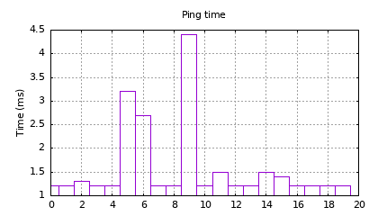
So the response time will vary, depending on the activity of any networks sharing the same WiFi channels; here is a a typical example of 20 pings, using the time reported on the Pico console:
Round-trip time for PicoWi ping
A ping time of 1.2 milliseconds is quite respectable, considering that a Pi 4 on the same network takes a minimum of 1.9 ms.
The graph was plotted using GNUplot; if you want to replicate it, the console output is captured to pings.txt, then pre-processed using awk:
This script should also work with the console output of Linux pings. The result is then fed to GNUplot; the command-line has been split into 4 for clarity:
gnuplot -e "set term png size 420,240 font 'sans,8'; \
  set title 'Ping time'; set grid; set key noautotitle; \
  set ylabel 'Time (ms)' offset 2; set output 'pings.png'; \
  plot 'pings.csv' with boxes"
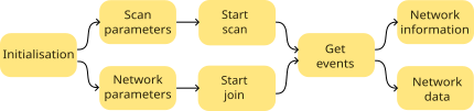
By the end of part 3, the WiFi chip was up & running, and as a simple test of WiFi operation, we’ll next scan the neighbourhood for WiFi networks, then attempt to join a network.
Scanning a network
As a quick check of wireless functionality, it can be useful to scan for WiFi networks within range. Before starting that, we need to send some IOCTL commands to configure various parameters, such as the network band.
The main problem with IOCTL calls is their sheer variety, that might require data in a specific format, or maybe no data at all. I haven’t been able to find a document that describes them, the only publicly-available documentation seems to be the source code . So when developing, it is quite possible to use the wrong IOCTL command, or send it the wrong data, and we need a way of reporting the error, without adding a lot of print function calls.
All my IOCTL functions return 0 if there wasn’t a reply, and -1 if the response indicated an error, so we can just chain commands using the short-circuit AND functionality to ensure execution will stop when an error occurs, and print the last IOCTL command that was executed:
We can check the code functioning by forcing an error, e.g. temporarily reducing the timeout value for a command such as ‘bcn_li_dtim’ to zero, in which case the code reports the following which, although somewhat terse, does indicate the source of the problem:
IOCTL error: cmd 263 SET bcn_li_dtim
To start a scan, we need one more IOCTL, with an data structure that sets some more parameters:
After that command is sent, we should receive several responses in the form of events; at least one from each WiFi network in range. The scan event handler has to byte-swap any 16 or 32-bit values, since they are in ‘network’ byte-order (big-endian); the handler function was described in the previous part of this blog.
It isn’t unusual for the same network to be reported more than once, e.g.
In the tests I have done, the total time from power-up to receiving the last scan entry is around 2.1 seconds, which is surprisingly fast, considering how much chip-initialisation has been required.
Joining a network
This requires a large number of IOCTL commands to set up the WiFi interface, and there is little point in my listing all of them here, so I’m concentrating on specific settings of interest.
Country: this is required in order to set domain-specific parameters. I’m taking the easy way out, and specifying a country code of ‘XX’, which is a common set of world-wide characteristics.
Multicast: there is one MAC address set to 01:00:5E:00:00:FB which is the standard for IP v4
Power saving: this is disabled by default, but can be compiled in if required, though it does significantly increase WiFi response times, as the device will sleep when idle, and takes some time to wake up & respond.
Authentication: this uses a WPA2 pre-shared key, stored in plaintext, which is a major weakness in network security.
Network name: the SSID is also stored as plaintext.
Once the network join has been initiated, we receive a stream of events to show progress. These can be viewed by calling set_display_mode with DISP_EVENT. A typical joining sequence might be:
Join secure network:
  Rx_EVT  87 ASSOC_REQ_IE,  flags 0, status 0, reason 0
  Rx_EVT   3 AUTH,          flags 0, status 0, reason 0
  Rx_EVT  88 ASSOC_RESP_IE, flags 0, status 0, reason 0
  Rx_EVT   7 ASSOC,         flags 0, status 0, reason 0
  Rx_EVT  16 LINK,          flags 1, status 0, reason 0
  Rx_EVT   1 JOIN,          flags 0, status 0, reason 0
  Rx_EVT   0 SET_SSID,      flags 0, status 0, reason 0
  Rx_EVT  46 PSK_SUP,       flags 0, status 6, reason 0
  ..then Rx_DATA for broadcast/multicast network traffic..

Automatic reassociation after joining a network:
  Rx_EVT  46 PSK_SUP,       flags 0, status 6, reason 14
  Rx_EVT  87 ASSOC_REQ_IE,  flags 0, status 0, reason 0
  Rx_EVT   3 AUTH,          flags 0, status 0, reason 0
  Rx_EVT  88 ASSOC_RESP_IE, flags 0, status 0, reason 0
  Rx_EVT   9 REASSOC,       flags 0, status 0, reason 0
  Rx_EVT  16 LINK,          flags 1, status 0, reason 0
  Rx_EVT  46 PSK_SUP,       flags 0, status 6, reason 0
  Rx_EVT   1 JOIN,          flags 0, status 0, reason 0
 ..then Rx DATA flow continues..

Join open network (no security):
  Rx_EVT  87 ASSOC_REQ_IE,  flags 0, status 0, reason 0
  Rx_EVT   3 AUTH,          flags 0, status 0, reason 0
  Rx_EVT  88 ASSOC_RESP_IE, flags 0, status 0, reason 0
  Rx_EVT   7 ASSOC,         flags 0, status 0, reason 0
  Rx_EVT  16 LINK,          flags 1, status 0, reason 0
  Rx_EVT   1 JOIN,          flags 0, status 0, reason 0
  Rx_EVT   0 SET_SSID,      flags 0, status 0, reason 0
  ..then Rx_DATA for broadcast/multicast network traffic..

SSID not found:
  Rx_EVT   0 SET_SSID,      flags 0, status 3, reason 0

Password incorrect:
  Rx_EVT  87 ASSOC_REQ_IE,  flags 0, status 0, reason 0
  Rx_EVT   3 AUTH,          flags 0, status 0, reason 0
  Rx_EVT  88 ASSOC_RESP_IE, flags 0, status 0, reason 0
  Rx_EVT   7 ASSOC,         flags 0, status 0, reason 0
  Rx_EVT  16 LINK,          flags 1, status 0, reason 0
  Rx_EVT   1 JOIN,          flags 0, status 0, reason 0
  Rx_EVT   0 SET_SSID,      flags 0, status 0, reason 0
  Rx_EVT  46 PSK_SUP,       flags 0, status 8, reason 15
  Rx_EVT  46 PSK_SUP,       flags 0, status 8, reason 14
  ..then the same sequence repeated..
The ‘status’ values are common to all the events:
0: success
3: no networks
6: unsolicited
8: partial
The ‘reason’ values are specific to an event, for example in PSK_SUP, 14 means that a de-authentication request has been received, and 15 indicates that a timeout of the pre-shared key handshake has occurred.
Also there is no guarantee that the events will arrive in this order; for example, when I tested on a different Access Point, the last 3 events were PSK_SUP, JOIN, and SET_SSID.
I have also tested the responses to network events:
Orderly shutdown of WiFi at the access point:
  Rx_EVT  12 DISASSOC_IND,  flags 0, status 0, reason 8
  Rx_EVT   3 AUTH,          flags 0, status 5, reason 0
  Rx_EVT  46 PSK_SUP,       flags 0, status 6, reason 0
  Rx_EVT  16 LINK,          flags 0, status 0, reason 2

Restore WiFi after orderly shutdown:
  Rx_EVT  87 ASSOC_REQ_IE,  flags 0, status 0, reason 0
  Rx_EVT   3 AUTH,          flags 0, status 0, reason 0
  Rx_EVT  88 ASSOC_RESP_IE, flags 0, status 0, reason 0
  Rx_EVT   9 REASSOC,       flags 0, status 0, reason 0
  Rx_EVT  16 LINK,          flags 1, status 0, reason 0
  Rx_EVT  46 PSK_SUP,       flags 0, status 6, reason 0
  Rx_EVT   1 JOIN,          flags 0, status 0, reason 0
  ..then the data flow resumes..

Power-down of the access point:
  Rx_EVT  16 LINK,          flags 0, status 0, reason 1

Restore power to the access point:
  Rx_EVT  16 LINK,          flags 0, status 0, reason 1
  Rx_EVT  87 ASSOC_REQ_IE,  flags 0, status 0, reason 0
  Rx_EVT   3 AUTH,          flags 0, status 0, reason 0
  Rx_EVT  88 ASSOC_RESP_IE, flags 0, status 0, reason 0
  Rx_EVT   9 REASSOC,       flags 0, status 0, reason 0
  Rx_EVT  16 LINK,          flags 1, status 0, reason 0
  Rx_EVT  46 PSK_SUP,       flags 0, status 6, reason 0
  Rx_EVT   1 JOIN,          flags 0, status 0, reason 0
  ..then the data flow resumes..

Network unavailable on startup:
  Rx_EVT   0 SET_SSID,      flags 0, status 3, reason 0

Network becomes available after startup:
  Nothing!

Try to join a secure network, using no security
  Rx_EVT   0 SET_SSID,      flags 0, status 0, reason 0
So the good news is that the WiFi chip can automatically reconnect to the network under some circumstances, but the bad news is that it will not always reconnect, and I can find no single event showing if the device is connected or not. Rather than attempting to decode the events in detail, I’ve used an overall timeout for joining a network (default 10 seconds); if that fails there is a rest period (currently also 10 seconds) before the next re-connection attempt.
Example programs
There are two examples; see the introduction for details of how to re-build and run the code.
scan.c does a single scan, and returns a list of networks found. The result returned by the WiFi chip is displayed as-is, so may contain duplicates.
join.c joins a given network, reporting on progress; the network name and password must be entered in the source code:
#define SSID                "testnet"
#define PASSWD              "testpass"
The on-board LED flashes at 5 Hz prior to connection, and at 1 Hz when connected.
In the next part I’ll start using TCP/IP protocols.
Part 2 described how the CYW43439 WiFi chip is initialised, but used an IOCTL call and an event check without explaining what these are, or how they work, so now is the time to rectify that deficiency.
An IOCTL (Input/Output Control) call is sent by the Pico host CPU (RP2040) to the ARM CPU in the WiFi chip, to read or write configuration data, or send a specific command. An event is an unsolicited block of data sent from the WiFi CPU to the host; it can be a notification that an action is complete, or some data that has arrived over the WiFi network.
IOCTLs
A simple example of an IOCTL is a request for the 6-byte WiFi MAC address.
This sends the IOCTL command GET_VAR, with a string to identify the item of interest, and a timeout in milliseconds.
#define WLC_GET_VAR 262

// Get data block from IOCTL variable
int ioctl_get_data(char *name, int wait_msec, uint8_t *data, int dlen)
{
    return(ioctl_cmd(WLC_GET_VAR, name, strlen(name)+1, wait_msec, false, data, dlen));
}
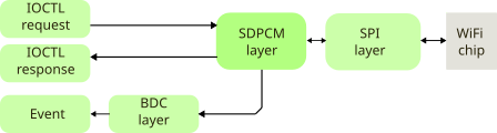
The request must be packed into a structure, for transmission the the WiFi CPU; this has 2 headers, the first is an ‘SDIO/SPI Bus Layer’ (SDPCM) header, followed by an IOCTL header:
The first two 16-bit words of the SDPCM header contain the data length, and its bitwise inverse, then the most important fields are:
Chan: a number identifying which ‘channel’ is associated with the data: IOCTL channel is 0, event is 1, and data is 2.
Hdrlen: the length of the SDPCM header plus any padding. My code doesn’t use any padding, but the response from the WiFi chip often has a lot of padding.
Flow & Credit: used to track the WiFi buffer utilisation
This is followed by the IOCTL header, with a command number (262 for GET_VAR) and a data length value.
The whole message plus data is written to the SPI interface:
// Do an IOCTL transaction, get response
// Return 0 if timeout, -1 if error response
int ioctl_cmd(int cmd, char *name, int namelen, int wait_msec, int wr, void *data, int dlen)
{
    IOCTL_CMD *cmdp = &ioctl_txmsg.cmd;
    int txdlen = ((namelen + dlen + 3) / 4) * 4, ret = 0;
    int hdrlen = sizeof(SDPCM_HDR) + sizeof(IOCTL_HDR);
    int txlen = hdrlen + txdlen;

    memset(cmdp, 0, sizeof(ioctl_txmsg));
    cmdp->sdpcm.notlen = ~(cmdp->sdpcm.len = txlen);
    cmdp->sdpcm.seq = sd_tx_seq++;
    cmdp->sdpcm.chan = SDPCM_CHAN_CTRL;
    cmdp->sdpcm.hdrlen = sizeof(SDPCM_HDR);
    cmdp->ioctl.cmd = cmd;
    cmdp->ioctl.outlen = txdlen;
    cmdp->ioctl.flags = ((uint32_t)ioctl_reqid++ << 16) | (wr ? 2 : 0);
    if (namelen)
        memcpy(cmdp->data, name, namelen);
    if (wr && dlen>0)
        memcpy(&cmdp->data[namelen], data, dlen);
    wifi_data_write(SD_FUNC_RAD, 0, (void *)cmdp, txlen);
    ..continued below..
The code now waits for a response, but it is important to note that the first response it receives may be associated with a completely different request, or network data. So it is essential to check that the response matches the command, and if not, keep on checking for a matching response.
    ..continued from above..
    while (wait_msec>=0 && !(ret=ioctl_resp_match(cmd, data, dlen)))
    {
        wait_msec -= IOCTL_POLL_MSEC;
        usdelay(IOCTL_POLL_MSEC * 1000);
    }
    return(ret);
}

// Read an ioctl response, match the given command, any command if 0
// Return 0 if no response, -1 if error response
int ioctl_resp_match(int cmd, void *data, int dlen)
{
    int rxlen=0, n=0, hdrlen;
    IOCTL_MSG *rsp = &ioctl_rxmsg;
    IOCTL_HDR *iohp;

    if ((rxlen = event_read(rsp, 0, 0)) > 0)
    {
        iohp = (IOCTL_HDR *)&rsp->data[rsp->cmd.sdpcm.hdrlen];
        hdrlen = rsp->cmd.sdpcm.hdrlen + sizeof(IOCTL_HDR);
        if (rsp->rsp.chan==SDPCM_CHAN_CTRL &&
            (cmd==0 || cmd==iohp->cmd))
        {
            n = MIN(dlen, rxlen-hdrlen);
            if (data && n>0)
                memcpy(data, &rsp->data[hdrlen], n);
            if (cmd)
            {
                if (iohp->status)
                    n = -1;
            }
        }
    }
    return(cmd==0 ? rxlen : n>0 ? n : 0);
}
You’ll note that the response has been obtained using the ‘event_read’ function, which handles all incoming data (solicited or unsolicited) from the WiFi interface; it will be described in detail below.
The IOCTL response has a similar format to the request, except that it generally has a lot of padding after the SDPCM header. This means that (unlike the transmit message) the receiver has to decode the SDPCM header ‘hdrlen’ value, in order to know how much padding has been added in front of the IOCTL header.
In addition to the IOCTL GET_VAR call that reads the value of a variable, given its name as a string, and its partner SET_VAR that writes a new value to that variable, there nearly 300 other IOCTL calls, such as SET_ANTDIV (command 64) which controls the antenna diversity, or UP (command 2) which is used to activate the WiFi interface.
Events
The WiFi chip signals an event when it has something to report to the host processor, for example it has succeeded in joining a WiFi network, or it has just received a data packet from that network.
As discussed above, there is a time-delay associated with any IOCTL command, so the IOCTL response might arrive within a stream of other events. So my code treats any incoming message as a potential event, and establishes its purpose by decoding the SDPCM header.
This raises the question of how the host CPU knows that there is an incoming event; the answer is that it can poll the BUS_SPI_STATUS_REG, to see if the ‘function 2 packet available’ flag is set. Alternatively, to avoid excessive polling cycles, the host can just check the IRQ line (described in part 1) and if that is high, there is an event pending. I use a combined approach; check the IRQ line, but is there hasn’t been any event for 10 milliseconds, check the status register:
#define SPI_STATUS_LEN_SHIFT            9
#define SPI_STATUS_LEN_MASK             0x7ff

// Get ioctl response, async event, or network data.
int event_get_resp(void *data, int maxlen)
{
    uint32_t val=0;
    int rxlen=0;

    val = wifi_reg_read(SD_FUNC_BUS, SPI_STATUS_REG, 4);
    if ((val != ~0) && (val & SPI_STATUS_PKT_AVAIL))
    {
        rxlen = (val >> SPI_STATUS_LEN_SHIFT) & SPI_STATUS_LEN_MASK;
        rxlen = MIN(rxlen, maxlen);
        // Read event data if present
        if (data && rxlen>0)
            wifi_data_read(SD_FUNC_RAD, 0, data, rxlen);
        // ..or clear interrupt, and discard data
        else
        {
            val = wifi_reg_read(SD_FUNC_BUS, SPI_INTERRUPT_REG, 2);
            wifi_reg_write(SD_FUNC_BUS, SPI_INTERRUPT_REG, val, 2);
            wifi_reg_write(SD_FUNC_BAK, SPI_FRAME_CONTROL, 0x01, 1);
        }
    }
    return(rxlen);
}
The status register has a flag to indicate data is available on function 2 (the radio interface), and also a length value, indicating how many bytes there are to read. Once that has been read in, the SDPCM header is checked, and the data after that header is copied into a buffer.
// Get ioctl response, async event, or network data
// Optionally copy data after SDPCM & BDC headers into a buffer, return its length
int event_read(IOCTL_MSG *rsp, void *data, int dlen)
{
    int rxlen=0, n=0, hdrlen;
    SDPCM_HDR *sdp=&rsp->cmd.sdpcm;
    BDC_HDR *bdcp;

    if ((rxlen = event_get_resp(rsp, sizeof(IOCTL_MSG))) >= sizeof(SDPCM_HDR)+sizeof(BDC_HDR))
    {
        if ((sdp->len ^ sdp->notlen) == 0xffff)
        {
            hdrlen = sdp->hdrlen;
            bdcp = (BDC_HDR *)&rsp->data[hdrlen];
            hdrlen += sizeof(BDC_HDR) + bdcp->offset*4;
            n = MIN(dlen, rxlen-hdrlen);
            if (data && n>0)
                memcpy(data, &rsp->data[hdrlen], n);
        }
    }
    return(dlen>0 ? (n>0 ? n : 0) : rxlen);
}
At the top of these function calls is the polling function, which stores the SDPCM values in a local structure (EVENT_INFO), and takes appropriate action with the data. The reason why a local structure is used is that the event header is in ‘network’ byte-order, which is big-endian (most-significant byte first), so the data is byte-swapped before being stored locally.
Since there may be multiple event handlers, and the the the polling function can’t know which one is the correct destination for the event, it calls each one in turn, stopping when one returns a non-zero value, indicating that it has accepted the event.
// Poll for async event, put results in info structure
int event_poll(void)
{
    EVENT_INFO *eip = &event_info;
    IOCTL_MSG *iomp = &ioctl_rxmsg;
    ESCAN_RESULT *erp=(ESCAN_RESULT *)rxdata;
    EVENT_HDR *ehp = &erp->eventh;
    int n = event_read(iomp, rxdata, sizeof(rxdata));

    if (n > 0)
    {
        eip->chan = iomp->rsp.sdpcm.chan;
        eip->flags = SWAP16(ehp->flags);
        eip->event_type = SWAP32(ehp->event_type);
        eip->status = SWAP32(ehp->status);
        eip->reason = SWAP32(ehp->reason);
        eip->data = rxdata;
        eip->dlen = n;
        if (eip->chan == SDPCM_CHAN_CTRL)
            display(DISP_EVENT, "\n");
        else if ((eip->chan==SDPCM_CHAN_EVT || eip->chan==SDPCM_CHAN_DATA) &&
            n >= sizeof(ETHER_HDR)+sizeof(BCMETH_HDR)+sizeof(EVENT_HDR))
            ok = event_handle(eip);
    }
    return(ok);
}
Handling an event
The code calls handler functions in turn, until one returns a non-zero value, indicating it has accepted the event.
#define MAX_HANDLERS    10
typedef int (*event_handler_t)(EVENT_INFO *eip);
event_handler_t event_handlers[MAX_HANDLERS];
int num_handlers;

// Run event handlers, until one returns non-zero
int event_handle(EVENT_INFO *eip)
{
    int ret=0;

    for (int i=0; i<num_handlers && !ret; i++)
        ret = event_handlers[i](eip);
    return(ret);
}
An event handler is called with a pointer to the EVENT_INFO structure, which basically contains a copy of the SDPCM header information (in the correct byte-order) and a pointer to the data after that header. The function must return zero if it hasn’t recognised the event. As an example, here is a simple handler that displays the result of a network scan:
// Handler for scan events
int scan_event_handler(EVENT_INFO *eip)
{
    ESCAN_RESULT *erp=(ESCAN_RESULT *)eip->data;
    int ret = eip->chan==SDPCM_CHAN_EVT && eip->event_type==WLC_E_ESCAN_RESULT;

    if (ret)
    {
        if (erp->eventh.status == 0)
        {
            printf("Scan complete\n");
            ret = -1;
        }
        else
        {
            printf("%s '", mac_addr_str(erp->info.bssid));
            disp_ssid(&erp->info.ssid_len);
            printf("' chan %d\n", SWAP16(erp->info.channel));
        }
    }
    return(ret);
}
Note that the ESCAN_RESULT data is in ‘network’ byte-order, so needs to be byte-swapped before being displayed.
This handler has to be added to the array of handlers using a function call:
add_event_handler(scan_event_handler);
This allows you to implement your own event handlers, in addition to, or instead of, the functions I have provided.
Enabling events
There are over 140 possible events, and by default they are disabled; we need to enable those we are interested in, such as network authentication & joining, so we can detect any problems.
The enabling process uses a (very large) bitfield, each bit indicating whether an event is enabled or disabled; the resulting byte array is sent to the WiFi CPU using an IOCTL call.
I have used an unusual method to specify the events that are to be enabled; a macro is used to store the event number, and a string corresponding to the event name. This means that I can display event names (instead of numbers) on a diagnostic console, which is very useful to show any problems.
// Storage for event number, and string for diagnostics
typedef struct {
    int num;
    char *str;
} EVT_STR;
#define EVT(e)      {e, #e}

const EVT_STR join_evts[]={EVT(WLC_E_JOIN), EVT(WLC_E_ASSOC), EVT(WLC_E_REASSOC),
    EVT(WLC_E_ASSOC_REQ_IE), EVT(WLC_E_ASSOC_RESP_IE), EVT(WLC_E_SET_SSID),
    EVT(WLC_E_LINK), EVT(WLC_E_AUTH), EVT(WLC_E_PSK_SUP),  EVT(WLC_E_EAPOL_MSG),
    EVT(WLC_E_DISASSOC_IND), EVT(WLC_E_DISASSOC_IND), EVT(-1)};
In the next part of this project we’ll be scanning and joining a network.
In part 1, I described the low-level hardware & software interface to the Broadcom / Cypress / Infineon CYW43439 WiFi chip, and its close relative, the CYW4343W.
Now we need to initialise the chip, so it is ready to receive network commands and data. This involves sending three files to the chip, and unfortunately there is no simple Application Programming Interface (API) to do this; it is necessary to send a detailed sequence of commands, and if there are any errors, you usually end up with a completely unresponsive WiFi chip.
The first step is to check the Active Low Power (ALP) clock; this involves setting a register, then waiting for the WiFi chip to acknowledge that setting.
This wait-and-loop scenario is quite common, so I’ve created a specific function for it:
// Check register value every msec, until correct or timeout
bool wifi_reg_val_wait(int ms, int func, int addr, uint32_t mask, uint32_t val, int nbytes)
{
    bool ok;

    while (!(ok=wifi_reg_read_check(func, addr, mask, val, nbytes)) && ms--)
        usdelay(1000);
    return(ok);
}

// Read & check a masked value, return zero if incorrect
bool wifi_reg_read_check(int func, int addr, uint32_t mask, uint32_t val, int nbytes)
{
    return((wifi_reg_read(func, addr, nbytes) & mask) == val);
}
A value is obtained from the register, masked with an AND-function, then compared with the required value. If the comparison is false, the code delays for one millisecond, then tries again, until the given time (in milliseconds) has expired.
This raises the question as to what the code should do when it encounters an error such as this; should it try to re-send the command? In practice, the timeout generally means that the internal state of the chip is incorrect; for example, there may have been a bug in the code, or a power glitch, and the only way to correct this situation is to re-power the chip, and start again – fortunately the initialisation process is quite fast (it only takes a few seconds) so this isn’t a major problem.
Assuming the ALP check passes, there are some more register write cycles that I can’t explain in detail, as I don’t have access to any information about the chip that isn’t publicly available.
We then make 2 writes to registers in banked memory, that do deserve more explanation.
The backplane function can only access a 32K block in the WiFi RAM, so the two addresses we’re writing (18004010 and 18004044 hex) are outside its access range, and we have to use bank-switching. There is a simple check to see if the bank has changed since the last access, in which case no switching is needed:
#define SB_32BIT_WIN    0x8000
#define SB_ADDR_MASK    0x7fff
#define SB_WIN_MASK     (~SB_ADDR_MASK)

// Set backplane window if address has changed
void wifi_bak_window(uint32_t addr)
{
    static uint32_t lastaddr=0;

    addr &= SB_WIN_MASK;
    if (addr != lastaddr)
        wifi_reg_write(SD_FUNC_BAK, BAK_WIN_ADDR_REG, addr>>8, 3);
    lastaddr = addr;
}

// Write a 1 - 4 byte value via the backplane window
int wifi_bak_reg_write(uint32_t addr, uint32_t val, int nbytes)
{
    wifi_bak_window(addr);
    return(wifi_reg_write(SD_FUNC_BAK, addr, val, nbytes));
}
We can now load the binary ARM firmware into the WiFi processor; it is in a file that is unique to the specific Wifi chip, so different files are needed for the CYW43439 and CYW4343w; these are the only differences in the way the chips are programmed.
As previously mentioned, the backplane can only access a 32K block, and each SPI access to the backplane is limited to 64 bytes, so the data loading function walks though the memory in 64-byte blocks, and when 32K is reached, the access window is moved up, and the loading resumes at address 0.
#define MAX_BLOCKLEN    64

// Load data block into WiFi chip (CPU firmware or NVRAM file)
int wifi_data_load(int func, uint32_t dest, const unsigned char *data, int len)
{
    int nbytes=0, n;
    uint32_t oset=0;

    wifi_bak_window(dest);
    dest &= SB_ADDR_MASK;
    while (nbytes < len)
    {
        if (oset >= SB_32BIT_WIN)
        {
            wifi_bak_window(dest+nbytes);
            oset -= SB_32BIT_WIN;
        }
        n = MIN(MAX_BLOCKLEN, len-nbytes);
        wifi_data_write(func, dest+oset, (uint8_t *)&data[nbytes], n);
        nbytes += n;
        oset += n;
    }
    return(nbytes);
}
After a delay to allow the WiFi chip to settle, the next item to be loaded is the non-volatile RAM (NVRAM) data. This is in the form of a C character array, with each entry being null-terminated, e.g.
Now it is necessary to reset the WiFi processor core, wait for the indication that the High Throughput (HT) clock is available, then wait for an ‘event’ that signals the device is ready. The most common fault I experienced when developing the code was that it gets stuck at this point, waiting for a confirmation that never comes.
// Reset, and wait for High Throughput (HT) clock ready
wifi_core_reset(false);
if (!wifi_reg_val_wait(50, SD_FUNC_BAK, BAK_CHIP_CLOCK_CSR_REG,
                              SD_HT_AVAIL, SD_HT_AVAIL, 1))
    return(false);
// Wait for backplane ready
if (!wifi_rx_event_wait(100, SPI_STATUS_F2_RX_READY))
    return(false);
Events are the main way that the WiFi chip sends signals or data asynchronously to the RP2040; for a detailed description of how they work, see the next part.
Once the system has signalled it is ready, the Country Locale Matrix (CLM) file has to be loaded. This binary file limits the WiFi parameters (e.g. transmit power level) to be within the regulatory constraints for the specific RF hardware and locale.
const unsigned char fw_clm_data[] = {
	0x42,0x4C,0x4F,0x42,0x3C,0x00,0x00,0x00,0xFA,0x69,0xE0,0xBB,
	0x01,0x00,0x00,0x00,0x02,0x00,0x00,0x00,0x00,0x00,0x00,0x00,
    ..and so on..
};
const unsigned int fw_clm_len = sizeof(fw_clm_data);

wifi_clm_load(fw_clm_data, fw_clm_len);
The loading function uses a specific structure to send IOCTL data blocks to the WiFi chip, with flags to mark the beginning & end of the sequence:
To show all this code in action, we can run our first complete program;
// PicoWi blinking LED test

#include <stdint.h>
#include <stdbool.h>
#include <stdio.h>
#include "picowi_pico.h"
#include "picowi_spi.h"
#include "picowi_init.h"

int main()
{
    uint32_t led_ticks;
    bool ledon=false;

    io_init();
    printf("PicoWi LED blink\n");
    set_display_mode(DISP_INFO);
    if (!wifi_setup())
        printf("Error: SPI communication\n");
    else if (!wifi_init())
        printf("Error: can't initialise WiFi\n");
    else
    {
        ustimeout(&led_ticks, 0);
        while (1)
        {
            if (ustimeout(&led_ticks, 500000))
                wifi_set_led(ledon = !ledon);
        }
    }
}
This sets up the WiFi chip as described above, prints the 6-byte MAC address, then just loops, flashing the LED that is attached to the Wifi chip at 1 Hz.
The display_mode function controls how much diagnostic information you might want to see, using a bitfield so you can combine multiple options:
This can potentially provide a lot of diagnostic information, the main limitation being the speed of the console display – I use a serial link at 460800 baud, since the default of 9600 is much too slow. To see some of the internal workings of PicoWi, try:
set_display_mode(DISP_INFO|DISP_REG|DISP_IOCTL);
You can call this function multiple times with different mode values, to concentrate the diagnostic information on a specific area of interest, and avoid displaying a lot of unwanted information while the WiFi chip is being initialised.
The other unusual feature is the use of the ustimeout function, which I’ve used it in place of the more conventional delay function call, as I don’t want the delay to block all other CPU activity. In a simple program this isn’t an issue, but in later examples I want to do other things (such as checking for events) while waiting for the LED to blink, so can’t use a simple delay.
The ustimeout function takes two arguments; a pointer to a variable, and a timeout value in microseconds (zero if immediate). When the specified time has elapsed, the function returns a non-zero value and reloads the variable with the current time. So you can add extra function calls to the main loop, without affecting the LED blinking.
The code to control the LED uses a single Device I/O Control (IOCTL) call with 2 arguments; the first is a bit-mask, and the second is the value:
#define SD_LED_GPIO     0

// Set WiFi LED on or off
void wifi_set_led(bool on)
{
    ioctl_set_intx2("gpioout", 10, 1<<SD_LED_GPIO, on ? 1<<SD_LED_GPIO : 0);
}
For details on how to build & run this example program, see the introduction.
IOCTL calls are the primary mechanism for high-level communication with the WiFi chip; see the next part for a detailed description.
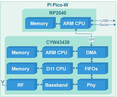
The WiFi interface on the Pico W uses the Broadcom/Cypress/Infineon CYW43439; this is a ‘full’ Media Access and Control (MAC) chip, so in theory you can just tell it to join a network, or send a block of data, and it’ll handle all the low-level operations.
However, in practice there is a lot more complication than that, and it takes a very large number of carefully-timed commands before the chip will start up, let alone do anything useful. This is because it actually contains two processors (ARM M3 and D11), each with their own memory and I/O, and they both have to be programmed before any network operations can start.
The CYW43439 is part of a large family of 43xxx wireless interfaces; most use PCI, USB or SDIO interface for communications with a host processor, but in this case communications is via a Serial Peripheral Interface (SPI) that is half-duplex, i.e. a single wire is used to carry commands & data to the WiFi chip, and also the responses from that chip, as described in the device datasheet.
SPI interface
Pi Pico W interface to CYW43439
This excerpt from the Pico-W circuit diagram shows the interface between the CYW43439 WiFi chip and the RP2040 CPU. The connections on the WiFi chip are labelled as if there were an SDIO interface, since they are dual-function:
SDIO function
SPI function
RP2040 pin
WL_REG_ON
Power up (ON)
GP23
SDIO_CLK
Clock (CLK)
GP29
SDIO_CMD
Data in (MOSI)
GP24
SDIO_DATA0
Data out (MISO)
GP24 via 470R
SDIO_DATA1
Interrupt (IRQ)
GP24 via 10K
SDIO_DATA2
Mode select (SEL)
GP24
SDIO_DATA3
Chip select (CS)
GP25
On chips with dual interfaces, the state of DATA2 at power-up determines which interface is to be used; for SPI, this pin must be held low, before REG_ON is set high to power up the chip.
A single data line is shared between CMD for commands & data going to the WiFi chip, and DATA0 for the returned responses. Just in case there is a clash of I/O (e.g. both the CPU and WiFi chip transmitting at the same time) there is a 470 ohm protection resistor in series with DATA0.
The chip-select line is as usual for SPI interfaces; when it is high, the WiFi interface is disconnected from the data lines. This allows the over-worked data line to be used for a third purpose, namely interrupt request (IRQ) to the RP2040 CPU; when the interface is idle, IRQ is normally low, but goes high when the WiFi chip has some data to send (e.g. a new data packet has been received). To ensure that the IRQ line doesn’t interfere with communications, it is connected via a 10K resistor.
Debug with CYW4343W
When developing this software, there was a major problem; the Pico-W components and PCB tracks are so fine that I couldn’t attach an oscilloscope or logic analyser to the SPI connections. This makes debugging the low-level drivers very difficult, especially when programming the PIO peripheral in the RP2040.
The solution I adopted was to add a second CYW43xxx interface to the Pico; unfortunately I couldn’t find a convenient CYW43439 module, but Avnet sell an FPGA add-on board (part number AES-PMOD-MUR-1DX-G) with a Murata 1DX module containing a CYW4343W. This is sufficiently similar to the 43439 that no code modifications are required, just a different firmware file, as described in part 2 of this post.
Circuitry to add Murata 1DX (CYW4343W) module to Pi Pico
I’ve had to tweak the resistor values slightly; this is because D0 – D4 pins on the module have 10K pullup resistors, so R2 has to be lower to compensate.
The choice of GPIO pins is completely arbitrary, since the code can work with any pin taking any function; I chose D0 – D3 as GP16 – GP19, since it will allow me to experiment with an SDIO interface at a future date. If you are only interested in emulating the standard Pico-W interface, then the connections to GP16 – GP18 can be omitted, since the SPI select line (D2) has a pull-down resistor.
The resulting circuitry fits very neatly onto a Pico prototyping board; by keeping the connections short, it works fine with SPI speeds up to 16 MHz. The only problems I encountered in constructing the hardware were that the PMOD connector has an unusual pin-numbering, and is mis-labelled as Bluetooth.
Pi Pico with Murata 1DX (CYW4343W) add-on module
Using this setup, it is easy to capture the SPI waveforms; here is an oscilloscope trace using a (relatively leisurely) 2 MHz clock for clarity.
SPI transfer waveforms
This shows a 4-byte command on the MOSI line, followed by a 4-byte MISO response, which also appears on the MOSI line, due to the 470 ohm resistor linking the two.
SPI software
Normally we’d just use the RP2040 built-in SPI controller to access the WiFi chip, but that has specific sets of pins it can use, which differ from those that are connected to the chip. This isn’t a major problem, as we can use the built-in Programmble I/O (PIO) to do the transfers, but initially I’d just like to check that the hardware works, before diving into PIO programming. So the first step is to write a ‘bit-bashed’ driver, that uses direct access to the I/O bits.
The write-cycle is quite conventional, where a bit (most-significant bit first) is put onto the data line, and the clock is toggled high then low:
// Write data to SPI interface
void spi_write(uint8_t *data, int nbits)
{
    uint8_t b=0;
    int n=0;

    io_mode(SD_CMD_PIN, IO_OUT);
    usdelay(SD_CLK_DELAY);
    b = *data++;
    while (n < nbits)
    {
        IO_WR(SD_CMD_PIN, b & 0x80);
        IO_WR(SD_CLK_PIN, 1);
        b <<= 1;
        if ((++n & 7) == 0)
            b = *data++;
        IO_WR(SD_CLK_PIN, 0);
    }
    usdelay(SD_CLK_DELAY);
    io_mode(SD_CMD_PIN, IO_IN);
    usdelay(SD_CLK_DELAY);
}
If the command is a data-read, the data is read immediately, then the clock is toggled high and low. This is unusual, and can cause confusion in some protocol decoders:
// Read data from SPI interface
void spi_read(uint8_t *data, int nbits)
{
    uint8_t b;
    int n=0;

    data--;
    while (n < nbits)
    {
        b = IO_RD(SD_DIN_PIN);
        IO_WR(SD_CLK_PIN, 1);
        if ((n++ & 7) == 0)
            *++data = 0;
        *data = (*data << 1) | b;
        IO_WR(SD_CLK_PIN, 0);
    }
 }
A write-cycle to the WiFi chip involves creating a command message as described in the data sheet, setting chip-select (CS) low, and transferring that message, followed by the data.
The unusual item is the function number, that selects which peripheral within the WiFi chip will receive the data; a value of 0 selects the SPI interface, 1 the backplane, and 2 the radio. Functions 0 & 1 are limited to a maximum size of 64 bytes, and are generally used for device configuration, whilst function 2 is used for transferring network data, which can be up to 2048 bytes. I’ve also created a dummy function 4, which is used to signal that a word-swap is required, when the chip is uninitialised.
The read cycle has a similar structure:
// Read data block using SPI
int wifi_data_read(int func, int addr, uint8_t *dp, int nbytes)
{
    SPI_MSG msg={.hdr = {.wr=0, .incr=1, .func=func&SD_FUNC_MASK,
                         .addr=addr, .len=nbytes}};
    uint8_t data[4];

    if (func & SD_FUNC_SWAP)
        msg.vals[0] = SWAP16_2(msg.vals[0]);
    else if (func == SD_FUNC_BAK)
        msg.hdr.len += 4;
    io_out(SD_CS_PIN, 0);
    usdelay(SD_CLK_DELAY);
    spi_write((uint8_t *)&msg, 32);
    io_mode(SD_CMD_PIN, IO_IN);
    usdelay(SD_CLK_DELAY);
    if (func == SD_FUNC_BAK)
        spi_read(data, 32);
    usdelay(SD_CLK_DELAY);
    spi_read(dp, nbytes*8);
    usdelay(SD_CLK_DELAY);
    io_mode(SD_CMD_PIN, IO_OUT);
    io_out(SD_CS_PIN, 1);
    return(nbytes);
}
When making a ‘backplane’ read, the first 4 return bytes are discarded; they are padding to give the remote peripheral time to respond.
Now that we have the necessary read/write functions, we can perform a simple check to see if the WiFi chip is responding. The data sheet describes several ‘gSPI registers’ and the ‘test read-only’ register at address 0x14 has the defined constant 0xFEEDBEAD. The first attempt to read this register generally fails, but subsequent reads should return the desired value:
#define SPI_TEST_VALUE 0xfeedbead
bool ok=0;
for (int i=0; i<4 && !ok; i++)
{
    usdelay(2000);
    val = wifi_reg_read(SD_FUNC_BUS_SWAP, 0x14, 4);
    ok = (val == SPI_TEST_VALUE);
}
if (!ok)
    printf("Error: SPI test pattern %08lX\n", val);
Next we need to configure the SPI interface to our preferences, using register 0, as described in the datasheet. The main change is to eliminate the awkward byte-swapping, but to do that, we need to send a byte-swapped command:
// Write a register using SPI
int spi_reg_write(int func, uint32_t addr, uint32_t val, int nbytes)
{
    if (func&SD_FUNC_SWAP && nbytes>1)
        val = SWAP16_2(val);
    return(wifi_data_write(func, addr, (uint8_t *)&val, nbytes));
}

wifi_reg_write(SD_FUNC_BUS_SWAP, SPI_BUS_CONTROL_REG, 0x204b3, 4);
Now we can re-read the test register without the awkward byte-swapping:
wifi_reg_read(SD_FUNC_BUS, 0x14, 4);
Another parameter we’ve set is ‘high-speed mode’, which means that reading & writing occur on the rising clock edge.
Using RP2040 PIO
To maximise the speed of SPI transfers, we need to use a peripheral within the RP2040 CPU. Normally this would be an SPI controller, but this can not control the pins that are connected to the WiFi chip, so we have to use the Programmable I/O (PIO) peripheral instead.
There are plenty of online tutorials explaining how PIO works; it is basically a small state-machine that is programmed in assembly-language. It operates in a highly deterministic fashion, at a rate of up to 125M instructions per second, so is ideally suited to handling the SPI interface.
I wanted to use the PIO as a direct replacement for the bit-bashed spi_read and spi_write functions described above, so the PIO program is:
; Pico PIO program for half-duplex SPI transfers
.program picowi_pio
.side_set 1
.wrap_target
.origin 0
public stall:               ; Stall here when transfer complete
    pull            side 0  ; Get byte to transmit from FIFO
loop1:
    nop             side 0  ; Idle with clock low
    in pins, 1      side 0  ; Fetch next Rx bit
    out pins, 1     side 0  ; Set next Tx bit
    nop             side 1  ; Idle high
    jmp !osre loop1 side 1  ; Loop if data in shift reg
    push            side 0  ; Save Rx byte in FIFO
.wrap
; EOF
The origin statement ensures the program is loaded at address zero, rather than the default, which is to load it at the top of program memory.
The ‘pull’ instruction fetches an 8-bit value from the transmit first-in first-out (FIFO) buffer, then there is a loop to output & input the individual bits of that byte until the transmit shift register is empty, and the receive register is full, so the latter can be pushed onto the receive FIFO.
So for SPI write, the associated C code just needs to keep the 4-entry transmit FIFO topped up with the outgoing data, and discard the incoming data, so the receive FIFO doesn’t overflow.
static PIO my_pio = pio0;
uint my_sm = pio_claim_unused_sm(my_pio, true);
io_rw_8 *my_txfifo = (io_rw_8 *)&my_pio->txf[0];

// Write data block to SPI interface,
// When complete, set data pin as I/P (so it is available for IRQ)
void pio_spi_write(unsigned char *data, int len)
{
    config_output(1);
    pio_sm_clear_fifos(my_pio, my_sm);
    while (len)
    {
        if (!pio_sm_is_tx_fifo_full(my_pio, my_sm))
        {
            *my_txfifo = *data++;
            len --;
        }
        if (!pio_sm_is_rx_fifo_empty(my_pio, my_sm))
            pio_sm_get(my_pio, my_sm);
    }
    while (!pio_sm_is_tx_fifo_empty(my_pio, my_sm) || !pio_complete())
    {
        while (!pio_sm_is_rx_fifo_empty(my_pio, my_sm))
            pio_sm_get(my_pio, my_sm);
    }
    pio_sm_get(my_pio, my_sm);
    config_output(0);
}
The SPI read code fills the transmit FIFO with null bytes, and fetches the incoming data from the receive FIFO:
// Read data block from SPI interface
void pio_spi_read(unsigned char *data, int rxlen)
{
    int txlen=rxlen;
    pio_sm_clear_fifos(my_pio, my_sm);
    while (rxlen > 0 || !pio_complete())
    {
        if (txlen>0 && !pio_sm_is_tx_fifo_full(my_pio, my_sm))
        {
            *my_txfifo = 0;
            txlen--;
        }
        if (!pio_sm_is_rx_fifo_empty(my_pio, my_sm))
        {
            *data++ = pio_sm_get(my_pio, my_sm);
            rxlen--;
        }
    }
}
Since the reading of a WiFi register involves an SPI write cycle closely followed by a read cycle, it is important that the write cycle is complete before the read cycle starts. This issue proved to be the biggest problem with the PIO code; it is easy to detect when the transmit FIFO is empty, but the code must carry on waiting until the last bit of the last byte has been shifted out. This means that I have to use an explicitly-coded loop in the assembly language, with a check of shift-register-empty, rather than using the auto-load capability of the input & output instructions.
The other tricky issue was how the assembly-language program should signal to the C program that the output-shift is complete. In theory, I can use an IRQ flag to do this signalling, but in practice I could not make that work reliably – the technique would only work at specific clock frequencies, which suggested that there might be a critical race between the two sets of code. The problem with timing-sensitive code is that a small unrelated change to the main program (e.g. addition of an interrupt) can cause the code to fail in a manner that is very difficult to diagnose, so it is essential that the code works reliably over a wide range of SPI frequencies.
The solution I adopted is encapsulated in the pio_complete function:
// Check to see if PIO transfer complete (stalled at FIFO pull)
static inline int pio_complete(void)
{
    return(my_pio->sm[my_sm].addr == picowi_pio_offset_stall);
}
This compares the current PIO execution address with the ‘stall’ label in the PIO code; if the transmit FIFO is empty, and this comparison is true, then the PIO is stalled waiting for more data, having shifted out everything it was given.
In a single-threaded program, it won’t be too difficult to keep the transmit FIFO topped up, and the receive FIFO emptied, so there is no risk of an overflow or underflow causing problems. However, this is more difficult when the program is multi-tasking, so it will be necessary to add Direct Memory Access (DMA) transfers to the current code.
Update: increasing SPI speed
The code-update has a much-improved SPI interface driver, which can achieve an SPI speed up to 62 MHz. There were 2 obstacles to achieving this speed; the first was the absence of DMA, which is easily rectified, then there was a more complicated issue due to the way the hardware is designed.
Direct Memory Access
DMA isn’t difficult, since the Pico SDK provides some really helpful functions, e.g. to set up transmission from a PIO channel:
I’ve chosen to stall (‘block’) the CPU until the DMA transfer is complete, but it could carry on executing code while the transfer progresses.
SPI speedup
Pi Pico-W interface to CYW43439
To save on I/O pins, the Pi Pico designer decided to use one pin to carry the incoming data from the CPU, the outgoing data to the CPU, and the interrupt signal. To avoid the possibility of an I/O clash when handling these 3 signals, the incoming & outgoing data pins aren’t directly connected together; there is a 470 ohm resistor in series with the data input.
In the previous code, we could ignore this resistor, since at a low data rate it has no real effect. However, as we increase the speed, the series resistance combines with the parallel (‘shunt’) capacitance to slow down the edges of the received data, resulting in errors. The obvious way to handle this is to slow the clock down, but since most SPI drivers work on the principle of simultaneously sending and receiving each byte, this means that SPI transmission is slowed down as well.
My solution is to split the SPI code into 2 separate functions, so the PIO either transmits or receives, and the slower reception doesn’t hinder the faster transmission.
The resulting PIO transmit code is simplified, so is much faster:
.origin 0
public stall: ; Stall here when transfer complete
; Write data to SPI (42 MHz SPI clock, if divisor is set to 1)
public writer:
pull side 0 ; Get byte to transmit from FIFO
wrloop:
nop side 0 ; Delay (if deleted, SPI clock is 63 MHz)
out pins, 1 side 0 ; Set next Tx bit
jmp !osre wrloop side 1 ; Loop if data in shift reg
.wrap
One of the difficulties with transmission is how to determine when it has completely finished, i.e. with both the FIFO and the shift register empty. For this reason I use an OSRE (output shift register empty) loop, such that I can detect when the transfer is complete using the pio_complete function described above.
As written above, the SPI runs at 41.7 MHz (125 MHz / 3), but it will also work at 62.5 MHz (125 MHz / 2) by deleting one of the ‘nop’ instructions, though this does violate the timing specification of the CYW43439, which is limited to 50 MHz. [Note: I am aware of the ability of the fractional divider to generate a more exact 50 MHz frequency, however this is done by inserting occasional delays into PIO instructions, so although the net data rate is 50 MHz, there are peaks of 62 MHz, so this still violates the timing specification].
The PIO read code is a lot more relaxed:
; Read data from SPI (25 MHz SPI clock, if divisor is set to 1)
public reader:
pull side 0 ; Get byte count from host FIFO
out x, 32 side 0 ; Copy into x register
byteloop:
set y, 7 side 0 ; For each bit in byte..
bitloop:
nop side 1 ; Delay
nop side 1
nop side 1
in pins, 1 side 0 ; Input SPI data bit
jmp y--, bitloop side 0 ; Loop until byte received
push side 0 ; Put byte in host FIFO
jmp x--, byteloop side 0 ; Loop until all bytes received
jmp reader side 0 ; Loop to start next transfer
This is triggered by putting a byte-count (minus 1) in the FIFO, then the code fetches that number of bytes, and DMA is used to transfer them into from the FIFO into memory. The code needs quite a bit of padding to be slow enough, so I haven’t used auto-push.
I originally put the transmit & receive code in separate PIO instances, but ran into problems with the interaction between the two – I couldn’t get them to share control of the I/O pins. So now I just use a single PIO instance, and select which program to execute by forcing a PIO ‘jump’ command before executing the code, e.g. for writing:
// Write data block to SPI interface
void wifi_spi_write(uint8_t *dp, int nbits)
{
pio_sm_clear_fifos(wifi_pio, wifi_sm);
pio_sm_exec(wifi_pio, wifi_sm, pio_encode_jmp(picowi_pio_offset_writer));
pio_sm_set_consecutive_pindirs(wifi_pio, wifi_sm, SD_CMD_PIN, 1, true);
dma_channel_transfer_from_buffer_now(wifi_tx_dma_chan, dp, nbits / 8);
dma_channel_wait_for_finish_blocking(wifi_tx_dma_chan);
}
The aim of this project is to provide a fast WiFi driver and TCP/IP stack for the CYW43439 chip on the Pi Pico W module, with C code running on the RP2040 processor; it can also be used with similar Broadcom / Cypress / Infineon chips that have an SPI interface, such as the CYW4343W.
It is based on my Zerowi project that performs a similar function on the Pi Zero device CYW43438, which has an SDIO interface. However, due to myriad difficulties getting the code running, the code has been restructured and simplified to emphasise the various stages in setting up the chip, and to provide copious run-time diagnostics.
The structured approach of the WiFi drivers is mirrored in the example programs, and the individual parts of this blog; they range from a simple LED-flash program, to one that provides TCP functionality.
A major problem with debugging Pico-W code is the difficulty attaching any hardware diagnostic tools, such as an oscilloscope or logic analyser; this has been addressed by supporting an add-on board with a Murata 1DX module and CYW4343W chip; full details are given in part 1 of this project.
Development environment
For simplicity, I use a Raspberry Pi 4 to build the code and program the Pico, with two I/O lines connected to the Pico SWD interface. This is really easy to set up, using a single script that installs the SDK and all the necessary software tools on the Pi 4:
For SWD programming, the Pico must be connected to the I/O pins on the Pi as follows:
Pico SWCLK   Pi pin 22 (GPIO 25)
Pico GND     Pi pin 20
Pico SWDIO   Pi pin 18 (GPIO 24)
The serial interface is used extensively for displaying diagnostic information; pin 1 of the Pico is the serial output, and pin 3 is ground. I use a 3.3 volt FTDI USB-serial adaptor to display the serial output on a PC, but the Pi 4 serial input could be used instead.
If you want to develop using a Windows PC, you can find several online guides as to how this might be set up, but I have experienced problems with the methods I tried. So far, the only good setup for Windows I’ve found is VisualGDB, which has a wide range of very useful features, but is not free.
The PicoWi source code is on github. To load it on the Pi 4:
cd ~
git clone http://github.com/jbentham/picowi
cd ~/picowi/build
chmod +x prog
chmod +x reset
I’ve included the necessary CMakeLists.txt, so the project can be built using the following commands:
cd ~/picowi/build
cmake ..      # create the makefiles
make picowi   # make the picowi library
make blink    # make the 'blink' application
./prog blink  # program the RP2040, and run the application
When building the current pico-SDK, there are some ‘parameter passing’ warnings when the pio assembler is compiled; these can be ignored.
Compilation is reasonably fast on the Pi 4; once the SDK libraries have been built, you can do a complete re-build of the PicoWi library and application within 10 seconds, and reprogram the RP2040 in under 3 seconds.
The ‘reset’ command is useful when you just want to restart the Pico, without loading any new code.
If OpenOCD reports ‘read incorrect DLIPDR’ then there is a problem with the wiring. I’ve set the SWD speed to 3 MHz, which should work error-free, providing the wires are sufficiently short (e.g. under 6 inches or 150 mm) and there are good power & ground connections between the Pi & Pico. I use a short USB cable to power the Pico from the Pi, and this is generally problem-free, though sometimes the Pi won’t boot with the Pico connected; this appears to be a USB communication problem.
Compile-time settings
There are two settings in the CMakeLists.txt file, one to choose between the on-board CYW43439 device, or an external CYW4343W module:
# Set to 0 for Pico-W CYW43439, 1 for Murata 1DX (CYW4343W)
set (CHIP_4343W 0)
The other enables or disables optimisation. It is necessary to disable compiler optimisation when debugging, as it makes the code execution difficult to follow, but it should be enabled for release code, as there is a significant speed improvement.
# Set debug or release version
set (RELEASE 1)
The Pico-specific settings are in picowi_pico.h:
#define USE_GPIO_REGS   0       // Set non-zero for direct register access
                                // (boosts SPI from 2 to 5.4 MHz read, 7.8 MHz write)
#define SD_CLK_DELAY    0       // Clock on/off delay time in usec
#define USE_PIO         1       // Set non-zero to use Pico PIO for SPI
#define PIO_SPI_FREQ    8000000 // SPI frequency if using PIO
These affect the way the SPI interface is driven; the default is to use the Pico PIO (programmable I/O) with the given clock frequency; 8 MHz is a conservative value, I have run it at 12MHz, and higher speeds should be possible with some tweaking of the I/O settings.
Setting USE_PIO to zero will enable a ‘bit-bashed’ (or ‘bit-banged’) driver; this can run over 7 MHz if using direct register writes, or 2 MHz if using normal function calls.
You’ll note that I haven’t included a driver for the SPI peripheral inside the RP2040; this would have been easier to use than the PIO peripheral, but the on-board CYW43439 chip isn’t connected to suitable I/O pins. The actual pins used are defined in picowi_pico.h:
You’ll see that pin 24 is performing multiple functions; this hardware configuration is discussed in detail in the next part of this blog. If you are using an external module, the pin definitions can be modified to use any of the RP2040 I/O pins.
Diagnostic settings
My code makes extensive use of a serial console for diagnostic purposes, and I generally use an FTDI USB-serial adaptor connected to pin 1 of the Pico module to monitor this, at the default 115K baud.
You can use the Pico USB link instead; it must be enabled in the CMakeLists.txt, using the name of the main file, for example to enable it for the ‘ping’ example program:
pico_enable_stdio_usb(ping 1)
Then you can use a terminal program such as minicom on the Pi 4 to view the console:
# Run minicom, press ctrl-A X to exit.
minicom -D /dev/ttyACM0 -b 115200
A disadvantage of this approach is that when the Pico is reprogrammed, its CPU is reset, which causes a failure of the USB link. After a few seconds, the link is re-established, but there will be a gap in the console display, which can be misleading. Also, the extra workload of maintaining a (potentially very busy) USB connection can cause timing problems, the CPU periodically going unresponsive while it services the USB link. So if you are making extensive use of the diagnostics, or are doing throughput tests, a hard-wired serial interface is strongly recommended.
You can control the extent to which diagnostic data is reported on the console; this is done by inserting function calls, rather than using compile-time definitions, to give fine-grained control. The display options are in a bitfield, so can be individually enabled or disabled, for example:
// Display SPI traffic details
set_display_mode(DISP_INFO|DISP_EVENT|DISP_SDPCM|
                 DISP_REG|DISP_JOIN|DISP_DATA);

// Display nothing
set_display_mode(DISP_NOTHING);

// Display ARP and ICMP data transfers
set_display_mode(DISP_ARP|DISP_IP|DISP_ICMP);
WiFi network
For the time being, the code does not support the Access Point functionality within the WiFi chip. It can only join a network that is unencrypted, or with WPA1 or WPA2 encryption, as set in the file picowi_join.h:
// Security settings: 0 for none, 1 for WPA_TKIP, 2 for WPA2
#define SECURITY            2
The network name (SSID) and password are defined in the ‘main’ file for each application, e.g. join.c or ping.c, which means they are insecure, as they can be seen by anyone with access to the source code or binary executable:
// Insecure password for test purposes only!!!
#define SSID                "testnet"
#define PASSWD              "testpass"
Other resources
The data sheets for the CYW43439 and CYW4343W are well worth a read, as they contain a good description of the low-level SPI interface, but contain nothing on the inner workings of these incredibly complicated chips. The Infineon WICED development environment has very comprehensive coverage of the WiFi chips, though it would take some work to port this code to the RP2040. The Pi Pico SDK contains the full source code to drive the CYW43439, with the lwIP (lightweight IP) open-source TCP/IP stack.
I’m using a different approach, with a completely new low-level driver, and a built-in TCP/IP stack to maximise throughput, as described in the following parts:
This is the third part of a 3-part blog post describing a low-cost WiFi-based logic analyser, that can be used for monitoring equipment in remote or hazardous locations. Part 1 described the hardware, part 2 the unit firmware, now this post describes the Web interface that controls the logic analyser units, and displays the captured data, also a Python class that can be used to remote-control the units for data analysis.
In a previous post, I experimented with shader hardware (via WebGL) for quickly displaying the logic analyser traces in a Web page. Whilst this technique can provide really fast display updates, there were some browser compatibility problems, and also a pure-javascript version proved to be fast enough, given that the main constraint is the time taken to transfer the data over the network.
So the current solution just used HTML and Javascript, with no hardware acceleration.
Network topology
REMLA network topology
In part 2, I described how the analyser units return data in response to Web page requests; the status information is in the form of a JSON string, and the sample data is Base64 encoded. So each unit has a built-in Web server, and it is tempting to load the HTML display files onto them. However, I chose not to do that, for the following reasons:
The analyser units use microcontrollers with finite resources, and not much spare storage space.
Every time the display software is updated, it would have to be loaded onto all the units individually.
It is easier to keep a single central server up-to-date with all the necessary security & access control measures.
So I’m assuming that there is a Web server somewhere on the system that serves the display file, and any necessary library files. This is a bit inconvenient for development, so when debugging I run a Web server on my development PC, for example using Python 3:
python -m http.server 8000
This launches a server on port 8000; if the display file is in a subdirectory ‘test’, its URL would look like:
http://127.0.0.1:8000/test/remla.html
There is also a question how the display program knows the addresses of the units, so it can access the right one. I had intended to use Multicast DNS (MDNS) for this purpose, but it proved to be a bit unreliable, so I assigned static IP addresses to the units instead.
Data display
The waveforms are drawn as vectors (as opposed to bitmaps), so the display can be re-sized to suit any size of screen. There are two basic drawing methods that can be used: an HTML canvas, or SVG (Scalable Vector Graphics). After some experimentation, I adopted the former, as it seemed to be a more flexible solution; the canvas is just an area of the screen that responds to simple line- and text-drawing commands, for example to draw & label the display grid:
var ctx1 = document.getElementById("canvas1").getContext("2d");
drawGrid(ctx1);

// Draw grid in display area
function drawGrid(ctx) {
  var w=ctx.canvas.clientWidth, h=ctx.canvas.clientHeight;
  var dw = w/xdivisions, dh=h/ydivisions;
  ctx.fillStyle = grid_bg;
  ctx.fillRect(0, 0, w, h);
  ctx.lineWidth = 1;
  ctx.strokeStyle = grid_fg;
  ctx.strokeRect(0, 1, w-1, h-1);
  ctx.beginPath();
  for (var n=0; n<xdivisions; n++) {
    var x = n*dw;
    ctx.moveTo(x, 0);
    ctx.lineTo(x, h);
    ctx.fillStyle = 'blue';
    if (n)
        drawXLabel(ctx, x, h-5);
    }
    for (var n=0; n<ydivisions; n++) {
      var y = n*dh;
      ctx.moveTo(0, y);
      ctx.lineTo(w, y);
    }
    ctx.stroke();
  }
Drawing the logic traces uses a similar method; begin a path, add line drawing commands to it, then invoke the stroke method.
Controls
The various control buttons and list boxes need to be part of a form, to simplify the process of sending their values to the analyser unit. So they are implemented as pure HTML:
To update the parameters on the unit, they are gathered from the form, and sent along with an optional command, e.g. cmd=1 to start a capture.
// Get form parameters
function formParams(cmd) {
  var formdata = new FormData(document.getElementById("captureForm"));
  var params = [];
  for (var entry of formdata.entries()) {
    params.push(entry[0]+ '=' + entry[1]);
  }
  if (cmd != null)
    params.push("cmd=" + cmd);
  return params;
}

// Get status from unit, optionally send command
function get_status(cmd=null) {
  http_request = new XMLHttpRequest();
  http_request.addEventListener("load", status_handler);
  http_request.addEventListener("error", status_fail);
  http_request.addEventListener("timeout", status_fail);
  var params = formParams(cmd), statusfile=remote_ip()+'/'+statusname;
  http_request.open( "GET", statusfile + "?" + encodeURI(params.join("&")));
  http_request.timeout = 2000;
  http_request.send();
}
The result of this HTTP request is handled by callbacks, for example if the request fails, there is a retry mechanism:
// Handle failure to fetch status page
function status_fail(e) {
  var evt = e || event;
  evt.preventDefault();
  if (retry_count < RETRIES) {
    addStatus(retry_count ? "." : " RETRYING")
    get_status();
    retry_count++;
  }
  else {
    doStop();
    redraw(ctx1);
  }
}
This mechanism was found to be necessary since very occasionally the remote unit fails to respond, for no apparent reason; if there is a real reason (e.g. it has been powered down) then the transfer is halted after 3 attempts.
If the status information has been returned OK, then a suitable action is taken; if a capture has been triggered, and the status page indicates that the capture is complete, then the data is fetched:
// Decode status response
function status_handler(e) {
  var evt = e || event;
  var remote_status = JSON.parse(evt.target.responseText);
  var state = remote_status.state;
  if (state != last_state) {
    dispStatus(state_strs[state]);
    last_state = state;
  }
  addStatus(".");
  if (state==STATE_IDLE || state==STATE_PRELOAD || state==STATE_PRETRIG || state==STATE_POSTTRIG) {
    repeat_timer = setTimeout(get_status, 500);
  }
  else if (remote_status.state == STATE_READY) {
    loadData();
  }
  else {
    doStop();
  }
}
Fetching data
Fetching the data is similar to fetching the status page, since it is a text file containing base64-encoded bytes. The callback converts the text into bytes, then pairs of bytes into an array of numeric values:
// Read captured data (display is done by callback)
function loadData() {
  dispStatus("Reading from " + remote_ip());
  http_request = new XMLHttpRequest();
  http_request.addEventListener("progress", capfile_progress_handler);
  http_request.addEventListener( "load", capfile_load_handler);
  var params = formParams(), capfile=remote_ip()+'/'+capname;
  http_request.open( "GET", capfile + "?" + encodeURI(params.join("&")));
  http_request.send();
}

// Display data (from callback event)
function capfile_load_handler(event) {
  sampledata = getData(event.target.responseText);
  doZoomReset();
  if (command == CMD_MULTI)
    window.requestAnimationFrame(doStart);
  else
    doStop();
}

// Get data from HTTP response
function getData(resp) {
  var d = resp.replaceAll("\n", "");
  return strbin16(atob(d));
}

// Convert string of 16-bit values to binary array
function strbin16(s) {
  var vals = [];
  for (var n=0; n<s.length;) {
    var v = s.charCodeAt(n++);
    vals.push(v | s.charCodeAt(n++) << 8);
  }
  return vals;
}
It is probable that this process could be streamlined somewhat, but currently the main speed restriction is the transfer of data from the ESP to the PC over the wireless network, so improving the byte-decoder wouldn’t give a noticeable speed improvement.
Saving the data
There needs to be some way of saving the sample data for further analysis; as it happens, the initial users of the system were already using the open-source Sigrok Pulseview utility for capturing data from small USB pods, so it was decided to save the data in the Sigrok file format.
This a basically a zipfile, with 3 components:
Metadata, identifying the channels, sample rate, etc.
Version, giving the file format version (currently 2)
Logic file, containing the binary data
The metadata format is quite easy to replicate, e.g.
[global]
sigrok version=0.5.1

[device 1]
capturefile=logic-1
total probes=16
samplerate=5 MHz
total analog=0
probe1=D1
probe2=D2
probe3=D3
..and so on until..
probe16=D16
unitsize=2
The dummy labels D1, D2 etc. are normally replaced with meaningful descriptions of the signals, followed by the unitsize parameter which gives the byte-width of the data, and marks the end of the labels.
The JSZip library is used to zip the various components together in a single file with the ‘sr’ extension:
function write_srdata(fname) {
  var meta = encodeMeta(), zip = new JSZip();
  var samps = new Uint16Array(sampledata);
  zip.file("metadata", meta);
  zip.file("version", "2");
  zip.file("logic-1-1", samps.buffer);
  zip.generateAsync({type:"blob", compression:"DEFLATE"})
  .then(function(content) {
    writeFile(fname, "application/zip", content);
  });
}

// Encode Sigrok metadata
function encodeMeta() {
  var meta=[], rate=elem("xrate").value + " Hz";
  for (var key in sr_dict) {
    var val = key=="samplerate" ? rate : sr_dict[key];
    meta.push(val[0]=='[' ? ((meta.length ? "\n" : "") + val) : key+'='+val);
  }
  for (var n=0; n<nchans; n++) {
    meta.push("probe"+(n+1) + "=" + (probes.length?probes[n]:n+1));
  }
  meta.push("unitsize=2");
  return meta.join("\n");
}
Configuration
So far, the only way the units can be configured is by using the browser controls, to set the sample rate, number of samples, threshold etc. Whilst this might be acceptable for a portable system, a semi-permanent installation needs some way of storing the configuration, including the naming of input channels on the display. Since there is a central Web server for the display files, can’t this also be used to store configuration files? The answer is ‘yes’, but there is then a question how these files can be modified in a browser-friendly way.
This is a bit difficult, since there are numerous security protections for the files on a server, to make sure they can’t be modified by a Web client. However, there is an extension to the HTTP protocol known as WebDAV (Web Distributed Authoring and Versioning), which does provide a mechanism for writing to files. Basically you need a general-purpose Web server that can be configured to support Web DAV (such as lighttpd, see this page), or alternatively a special-purpose server, such as wsgidav (see this page).
Assuming you already have a working lighttpd server, the additional configuration file may look something like this, with some_path, dav_username and dav_password being customised for your installation:
Again, this will need to be customised for your environment, and you also need to be mindful that the configurations I’ve shown for lighttpd and wsgidav are quite insecure, for example the password isn’t encrypted, so it can easily be captured by anyone snooping on network traffic.
Configuration Web page
I created a simple Web page to handle the configuration, with list boxes for most options, and text boxes to allow the input channels to be named.
At the bottom of the page there are buttons to submit the new configuration to the server, and exit back to the waveform display page.
The key Javascript function to save the configuration on the server uses the ‘davclient’ library, and is quite simple, but it does need to know the host IP address and port number to receive the data. This code attempts to fetch that information using the DOM Location object:
// Save the config file
function saveConfig() {
  var fname = CONFIG_UNIT.replace('$', String(unitNum()));
  var ip = location.host.split(':')
  var host = ip[0], port = ip[1];
  port = !port ? 80 : parseInt(port);
  var davclient = new davlib.DavClient();
  davclient.initialize(host, port, 'http', DAVUSER, DAVPASS);
  davclient.PUT(fname, JSON.stringify(getFormData()), saveHandler)
 }
For simplicity, the DAV username and password are stored as plain text in the Javascript, which means that anyone viewing the page source can see what they are. This makes the server completely insecure, and must be improved.
Python interface
Although some data analysis can be done in Javascript, it is much more convenient to use Python and its numerical library numpy. I have written a Python class EdlaUnit that provides an API for remote control and data analysis, and a program edla_sweep that demonstrates this functionality.
It repeatedly captures a data block, whilst stepping up the threshold voltage. Then for each block, the number of transitions for each channel is counted and displayed.
import edla_utils as edla, base64, numpy as np

edla.verbose_mode(False)
unit = edla.EdlaUnit(1, "192.168.8")
unit.set_sample_rate(10000)
unit.set_sample_count(10000)

MIN_V, MAX_V, STEP_V = 0, 50, 5

def get_data():
    ok = False
    data = None
    status = unit.fetch_status()
    if status:
        ok = unit.do_capture()
    else:
        print("Can't fetch status from %s" % unit.status_url)
    if ok:
        data = unit.do_load()
    if data == None:
        print("Can't load data")
    return data

for v in range(MIN_V, MAX_V, STEP_V):
    unit.set_threshold(v)
    d = get_data()
    byts = base64.b64decode(d)
    samps = np.frombuffer(byts, dtype=np.uint16)
    diffs = np.diff(samps)
    edges = np.where(diffs != 0)[0]
    totals = np.zeros(16, dtype=int)
    for edge in edges:
        bits = samps[edge] ^ samps[edge+1]
        for n in range(0, 15):
            if bits & (1<<n):
                totals[n] += 1
    s = "%4u," % v
    s += ",".join([("%4u" % val) for val in totals])
    print(s)
The idea is to give a quick overview of the logic levels the analyser is seeing, to make sure they are within reasonable bounds. An example output is:
The absolute count isn’t necessarily very important, since it will vary depending on the signal that is being monitored. What is interesting is the way it changes as the threshold voltage increases. If the number dramatically increases as the ‘1’ logic voltage is approached, one might suspect that there is a noise problem, causing spurious edges. Conversely, if the value declines rapidly before the ‘1’ voltage is reached, the logic level is probably too low.
There is a tendency to assume that all logic signals are a perfect ‘1’ or ‘0’, with nothing in between; this technique allows you to look beyond that, and check whether your signals really are that perfect – and of course you can use the power of Python and numpy to do other analytical tests, or protocol decoding, specific to the signals being monitored.
—
Part 1 of this project looked at the hardware, part 2 the ESP32 firmware. The source files are on Github.
Copyright (c) Jeremy P Bentham 2022. Please credit this blog if you use the information or software in it.