The nRF52832 is an ARM Cortex M4 chip with an impressive range of peripherals, including an on-chip 2.4 GHz wireless transceiver. Nordic supply a comprehensive SDK with plenty of source-code examples; they are fully compatible with the GCC compiler, but there is little information on how to program and debug a target system using open-source tools such as the GDB debugger, or the OpenOCD JTAG/SWD programmer.
This blog will show you how to compile, program and debug some simple examples using the GNU ARM toolchain; the target board is the NRF52832 Breakout from Sparkfun, and the programming is done via a Nordic development board, or OpenOCD on a Raspberry Pi. Compiling & debugging is with GCC and GDB, running on Windows or Linux.
Source files

All the source files are in an ‘nrf_test’ project on GitHub; if you have Git installed, change to a suitable project directory and enter:
git clone https://github.com/jbentham/nrf_test
Alternatively you can download a zipfile from github here. You’ll also need the nRF5 15.3.0 SDK from the Nordic web site. Some directories need to be copied from the SDK to the project’s nrf5_sdk subdirectory; you can save disk space by only copying components, external, integration and modules as shown in the graphic above.
Windows PC hardware

The standard programming method advocated by Nordic is to use the Segger JLink adaptor that is incorporated in their evaluation boards, and the Windows nRF Command Line Tools (most notably, the nrfjprog utility) that can be downloaded from their Web site.
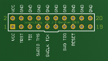
Connection between the evaluation board and target system can be a bit tricky; the Sparkfun breakout board has provision for a 10-way Cortex Debug Connector, and adding the 0.05″ pitch header does require reasonable soldering skills. However, when that has been done, a simple ribbon cable can be used to connect the two boards, with no need to change any links or settings from their default values.
One quirk of this arrangement is that the programming adaptor detects the 3.3V power from the target board in order to switch the SWD interface from the on-board nRF52 chip to the external device. This has the unfortunate consequence that if you forget to power up the target board, you’ll be programming the wrong device, which can be confusing.
The JLink adaptor isn’t the only programming option for Windows; you can use a Raspberry Pi with OpenOCD installed…
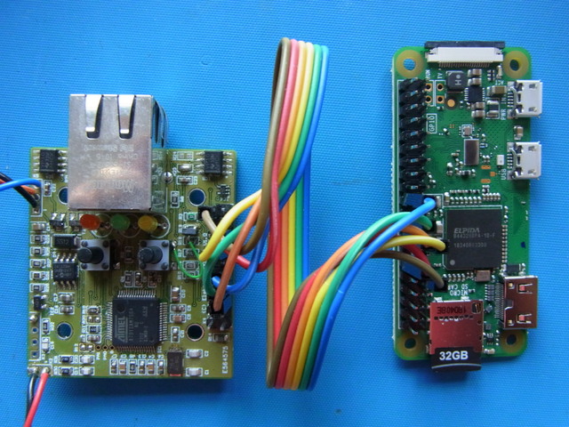
Raspberry Pi hardware

In a previous blog, I described the use of OpenOCD on the raspberry Pi; it can be used as a Nordic device programmer, with just 3 wires: ground, clock and data – the reset line isn’t necessary. The breakout board needs a 5 volt supply which could be taken from the RPi, but take care: accidentally connecting a 5V signal to a 3.3V input can cause significant damage.


Install OpenOCD as described in the previous blog; I’ve included the RPi and SWD configuration files in the project openocd directory, so for the RPi v2+, run the commands:
cd nrf_test
sudo openocd -f openocd/rpi2.cfg -f openocd/nrf52_swd.cfg
The response should be..
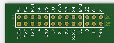
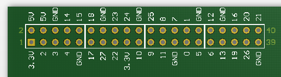
BCM2835 GPIO config: tck = 25, tms = 24, tdi = 23, tdo = 22

Info : Listening on port 6666 for tcl connections
Info : Listening on port 4444 for telnet connections
Info : BCM2835 GPIO JTAG/SWD bitbang driver
Info : JTAG and SWD modes enabled
Info : clock speed 1001 kHz
Info : SWD DPIDR 0x2ba01477
Info : nrf52.cpu: hardware has 6 breakpoints, 4 watchpoints
Info : Listening on port 3333 for gdb connections
The DPIDR value of 0x2BA01477 is correct for the nRF52832 chip; if any other value appears, there is a problem: check the wiring.
Windows development tools
The recommended compiler toolset for the SDK files is gcc-arm-none-eabi, version 7-2018-q2-update, available here. This places the tools in the directory
C:\Program Files (x86)\GNU Tools Arm Embedded\7 2018-q2-update\bin
Check that this directory in included in your search path by opening a command window, and typing
arm-none-eabi-gcc -v
If not found, close the window, add to the PATH environment variable, and retry.
You will also need to install Windows ‘make’ from here. At the time of writing, the version is 3.81, but I suspect most modern versions would work fine. As with GCC, check that it is included in your executable path by opening a new command window, and typing
make -v
Linux development tools
A Raspberry Pi 2+ is quite adequate for compiling and debugging the test programs.
Although RPi Linux already has an ARM compiler installed, the executable programs it creates are heavily dependant on the operating system, so we also need to install a cross-compiler: arm-none-eabi-gcc version 7-2018-q2-update. The easiest way to do this is to click on Add/Remove software in the Preferences menu, then search for arm-none-eabi. The correct version is available on Raspbian ‘Buster’, but probably not on earlier distributions.
The directory structure is the same as for Windows, with the SDK components, external, integration and modules directories copied into the nrf5_sdk subdirectory.

As with Windows, it is worth typing
arm-none-eabi-gcc -v
..to make sure the GCC executable is installed correctly.
nrf_test1.c
This is in the nrf_test1 directory, and is as simple as you can get; it just flashes the blue LED at 1 Hz.
// Simple LED blink on nRF52832 breakout board, from iosoft.blog

#include "nrf_gpio.h"
#include "nrf_delay.h"

// LED definitions
#define LED_PIN      7
#define LED_BIT      (1 << LED_PIN)

int main(void)
{
    nrf_gpio_cfg_output(LED_PIN);

    while (1)
    {
        nrf_delay_ms(500);
        NRF_GPIO->OUT ^= LED_BIT;
    }
}

// EOF
An unusual feature of this CPU is that the I/O pins aren’t split into individual ports, there is just a single port with a bit number 0 – 31. That number is passed to an SDK function to initialise the LED O/P pin, and I could have used another SDK function to toggle the pin, but instead used an exclusive-or operation on the hardware output register.
The SDK delay function is implemented by performing dummy CPU operations, so isn’t particularly accurate.
Compiling
For both platforms, the method is the same: change directory to nrf_test1, and type ‘make’; the response should be similar to:
Assembling ../nrf5_sdk/modules/nrfx/mdk/gcc_startup_nrf52.S
 Compiling ../nrf5_sdk/modules/nrfx/mdk/system_nrf52.c
 Compiling nrf_test1.c
 Linking build/nrf_test1.elf
    text    data     bss     dec     hex filename
..for Windows..
    1944     108      28    2080     820 build/nrf_test1.elf
..or for Linux..
    2536     112     172    2820     b04 build/nrf_test1.elf
If your compile-time environment differs from mine, it shouldn’t be difficult to change the Makefile definitions to match, but there are some points to note:
- The main changeable definitions are towards the top of the file. Resist the temptation to rearrange CFLAGS or LNFLAGS, as this can create a binary image that crashes the target system.
- You can add files to the SRC_FILES definition, they will be compiled and linked in; the order of the files isn’t significant, but I generally put gcc_startup_nrf52.S first, so Reset_Handler is at the start of the executable code. Similarly, INC_FOLDERS can be expanded to include any other folders with your .h files.
- The task definitions toward the bottom of the file use the tab character for indentation. This is essential: if replaced with spaces, the build process will fail.
- ELF, HEX and binary files are produced in the ‘build’ subdirectory; ELF is generally used with GDB, while HEX is required by the JLink flash programmer.
- I’ve defined the jflash and ocdflash tasks, that do flash programming after the ELF target is built; you can add your own custom programming environment, using a similar syntax.
- The makefile will re-compile any C source files after they are changed, but will not automatically detect changes to the ‘include’ files, or the makefile itself; when these are edited, it will be necessary to force a re-make using ‘make -B’.
- If a new image won’t run on the target system, the most common reason is an un-handled exception, and it can be quite difficult to find the cause. So I’d recommend that you expand the code in relatively small steps, making it easier to backtrack if there is a problem.
Device programming
Having built the binary image, we need to program it into Flash memory on the target device. This can be done by:
- JLink adaptor on an evaluation board (Windows PC only)
- Directly driving OpenOCD (RPi only)
- Using the GNU debugger GDB to drive OpenOCD (both platforms)
Device programming using JLink
Set up the hardware and install the Nordic nRF Command Line Tools as described above, then the nrfjflash utility can be used to program the target device with a hex file, e.g.
nrfjprog --program build/nrf_test1.hex --sectorerase
nrfjprog --reset
The second line resets the chip after programming, to start the program running. This is done via the SWD lines, a hardware reset line isn’t required; alternatively you can just power-cycle the target board.
The above commands have been included in the makefile, so if you enter ‘make jflash’, the programming commands will be executed after the binary image is built.
An additional usage of the JLink programmer is to restore the original Arduino bootloader, that was pre-installed on the Sparkfun board. To do this, you need to get hold of the softdevice and DFU files from the Sparkfun repository, combine them using the Nordic merge utility, then program the result using a whole-chip erase:
mergehex -m s132_nrf52_2.0.0_softdevice.hex sfe_nrf52832_dfu.hex -o dfu.hex
nrfjprog --program dfu.hex --chiperase
nrfjprog --reset
Device programming using OpenOCD
OpenOCD can be used to directly program the target device, providing the image has been built on the Raspberry Pi, or the ELF file has been copied from the development system. Install and test OpenOCD as described in the Raspberry Pi Hardware section above (check the DPIDR value is correct), hit ctrl-C to terminate it, then enter the command:
sudo openocd -f ../openocd/rpi2.cfg -f ../openocd/nrf52_swd.cfg -c "program build/nrf_test1.elf verify reset exit"
The response should be similar to:
 ** Programming Started **
 Info : nRF52832-QFAA(build code: E0) 512kB Flash
 Warn : using fast async flash loader. This is currently supported
 Warn : only with ST-Link and CMSIS-DAP. If you have issues, add
 Warn : "set WORKAREASIZE 0" before sourcing nrf51.cfg/nrf52.cfg to disable it
 ** Programming Finished **
 ** Verify Started **
 ** Verified OK **
 ** Resetting Target **
 shutdown command invoked
Note the warnings: by default, OpenOCD uses a ‘fast async flash loader’ that achieves a significant speed improvement by effectively sending a write-only data stream. Unfortunately the Nordic chip occasionally takes exception to this, and returns a ‘wait’ response, which can’t be handled in fast async mode, so the programming fails – in my tests with small binary images, it does fail occasionally. As recommended in the above text, I’ve tried adding ‘set WORKAREASIZE 0’ to nrf52_swd.cfg (before ‘find target’), but this caused problems when using GDB. By the time you read this, the issue may well have been solved; if not, you might have to do some experimentation to get reliable programming.
The makefile includes the OpenOCD direct programming commands, just run ‘make ocdflash’.
Device programming using GDB and OpenOCD
The primary reason for using GDB is to debug the target program, but it can also serve as a programming front-end for OpenOCD. This method works with PC host, or directly on the RPi, as shown in the following diagram.
In both cases we are using the GB ‘target remote’ command; on the development PC we have to specify the IP address of the RPi: for example, 192.168.1.2 as shown above. If in doubt as to the address, it is displayed if you hover the cursor over the top-right network icon on the RPi screen. By default, OpenOCD only responds to local GDB requests, so the command ‘bindto 0.0.0.0’ must be added to the configuration. This means anyone on the network could gain control of OpenOCD, so use with care: consider the security implications.
Alternatively, the Raspberry Pi can host both GDB and OpenOCD, in which case the ‘localhost’ address is used, and there is no need for the additional ‘bindto’.
The commands for the PC-hosted configuration are:
# On the RPi:
  sudo openocd -f ../openocd/rpi2.cfg -f ../openocd/nrf52_swd.cfg -c "bindto 0.0.0.0"

# On the Windows PC:
arm-none-eabi-gdb -ex="target remote 192.168.1.2:3333" build\nrf_test1.elf -ex "load" -ex "det" -ex "q"
The PC connects to the OpenOCD GDB remote server on port 3333, loads the file into the target flash memory, detaches from the connection, and exits. The response will be something like:
Loading section .text, size 0x790 lma 0x0
 Loading section .ARM.exidx, size 0x8 lma 0x790
 Loading section .data, size 0x6c lma 0x798
 Start address 0x2b4, load size 2052
 Transfer rate: 4 KB/sec, 684 bytes/write.
 Detaching from program: c:\Projects\nrf_test\nrf_test1\build\nrf_test1.elf, Remote target
 Ending remote debugging.
I have experienced occasional failures with the message “Error finishing flash operation”, in which case the command must be repeated; see my comments on the ‘fast async flash loader’ above.
The Rpi-hosted command sequence is similar:
# On the RPi (first terminal):
sudo openocd -f ../openocd/rpi2.cfg -f ../openocd/nrf52_swd.cfg

# On the RPi (second terminal):
gdb -ex="target remote localhost" build\nrf_test1.elf -ex "load" -ex "det" -ex "q"
Note that the GDB programming cycle does not include a CPU reset, so to run the new program the target reset button must be pressed, or the board power-cycled.
nrf_test2.c
There are many ways the first test program can be extended, I chose to add serial output (including printf), and also a timeout function based on the ARM systick timer, so the delay function doesn’t hog the CPU. The main loop is:
int main(void)
{
    uint32_t tix;

    mstimeout(&tix, 0);
    init_gpio();
    init_serial();
    printf("\nNRF52 test\n");
    while (1)
    {
        if (mstimeout(&tix, 500))
        {
            NRF_GPIO->OUT ^= LED_BIT;
            putch('.');
        }
        poll_serial();
    }
}
I encountered two obstacles; firstly, I ran out of time trying to understand how to create a non-blocking serial transmit routine using the SDK buffering scheme, so implemented a simple circular buffer that is polled for transmit characters in the main program loop.
The second obstacle was that the CPU systick is a 24-bit down-counter clocked at 64 MHz, which means that it wraps around every 262 milliseconds. So we can’t just use the counter value to check when 500 milliseconds has elapsed, it needs some creative coding to measure that length of time; with hindsight, it might have been better to use a conventional hardware timer.
To build the project just change directory to nrf_test2, and use ‘make’ as before. The source code is fairly self explanatory, but the following features are a bit unusual:
- For printf serial output, the Arduino programming link on the 6-way connector can’t be used, so we have to select an alternative.
- A remarkable feature of the UART is that we can choose any unused pin for I/O; the serial signals aren’t tied to specific pins. I’ve arbitrarily chosen I/O pin 15 for output, 14 for input.
- The method of initialising the UART and the printf output is also somewhat unusual, in that it involves a ‘context’ structure with the overall settings, in addition to the configuration structure.
Viewing serial comms


The serial output from the target system I/O pin 15 is a 3.3V signal, that is compatible with the serial input pin 10 (BCM 15) on the RPi (TxD -> RxD). To enable this input, launch the Raspberry Pi Configuration utility, select ‘interfaces’, enable the serial port, disable the serial console, and reboot.
To view the serial data, you could install a comms program such as ‘cutecom’, or just enter the following command line in a terminal window (ctrl-C to exit):
stty -F /dev/ttyS0 115200 raw; cat /dev/ttyS0
Debugging
We have already used GDB to program the target system, a similar setup can be used for debugging. Some important points:
- You’ll be working with 2 binary images; one that is loaded into GDB, and another that has been programmed into the target, and these two images must be identical. If in doubt, you need to reprogram the target.
- The .elf file that is loaded into GDB contains the binary image and debug symbols, i.e.the names and addresses of your functions & variables. You can load in a .hex file instead, but that has no symbolic information, so debugging will be very difficult.
- Compiler optimisation is normally enabled (using the -O3 option) as it generates efficient code, but this code is harder to debug, since there isn’t a one-to-one correspondence between a line of source and a block of instructions. Disabling optimisation will make the code larger and slower, but easier to debug; to do this, comment out the OPTIMISE line in the makefile (by placing ‘#’ at the start) and rebuild using ‘make -B’
- OpenOCD must be running on the Raspberry Pi, configured for SWD mode and the NRF52 processor (files rpi2.cfg and nrf52_swd.cfg). It will be fully remote-controlled from GDB, so won’t require any other files on the RPi.
- GDB must be invoked in remote mode, with “target remote ADDR:3333” where ADDR is the IP address of the Raspberry Pi, or localhost if GDB and OpenOCD are running on the same machine.
- GDB commands can be abbreviated providing there is no ambiguity, so ‘print’ can be shortened to ‘p’. Some commands can be repeated by hitting the Enter key, so if the last command was ‘step’, just hit Enter to do another step.
- When stepping through code, the main command letters you need to remember are ‘s’ for a single source-line step, ‘n’ for the next source line (executing any intervening function calls, but not stopping in them) and ‘f’ to execute the current function to its finish, and halt on return to the caller.
Here is a sample debugging session (user commands in bold):
# On the RPi:
sudo openocd -f ../openocd/rpi2.cfg -f ../openocd/nrf52_swd.cfg -c "bindto 0.0.0.0"

# On the PC, if RPi is at 192.168.1.2:
arm-none-eabi-gdb -ex="target remote 192.168.1.2:3333" build/nrf_test2.elf
Target system halts, current source line is shown

# Program binary image into target system
load
Loading section .text, size 0x215c lma 0x0
Loading section .log_const_data, size 0x10 lma 0x215c
..and so on..

# Print Program Counter (should be at reset handler)
p $pc
$1 = (void (*)()) 0x2b4 <Reset_Handler>

# Execute program (continue)
c

# Halt program: hit ctrl-C, target reports current location
ctrl-C
Program received signal SIGINT, Interrupt.
 main () at nrf_test2.c:72
 72              poll_serial();

# Print millisecond tick count
p msticks
$3 = 78504

# Print O/P port value in hex
p/x NRF_GPIO->OUT
$4 = 0x8080

# Toggle LED pin on O/P port
set NRF_GPIO->OUT ^= 1<<7

# Restart the program from scratch, with breakpoint
set $pc=Reset_Handler
b putch
c
Breakpoint 1, putch (c=13) at nrf_test2.c:149
 149         int in=ser_txin+1;

# Single-step, and print a local variable
s
151         if (in >= SER_TX_BUFFLEN)
p in
$5 = 46

# Detach from remote, and exit
det
quit
Next step
I guess the next step is to get wireless communications working, watch this space…
Copyright (c) Jeremy P Bentham 2019. Please credit iosoft.blog if you use the information or software in here.