PicoWi Mg: running Mongoose TCP/IP on the Pi Pico W

Sample page from Mongoose Web server

Mongoose TCP/IP is comprehensive easy-to-use TCP/IP software stack, produced by Cesanta Software Ltd.

In its simplest form, you just include 2 library files in your project, then can add a Web server using only 20 lines of source code, see the details here. The code is fully open-source, and the documentation is excellent; the only downside for some projects might be that a (low cost) license is required for commercial usage, but this is a reasonable request, given the amount of work that has gone into this high-quality package. Non-commercial projects can use the software for free, within the standard GPL licensing conditions.

The package supports the Pi Pico RP2040 CPU as standard, and there is an example program using the Wiznet W5500 Ethernet controller, the source code is available here. There is also an example of WiFi connectivity on the Pico-W, using the standard Raspberry Pi Application Programming Interface (API) but the result is quite complex, so I’ve replaced that API with my high-speed WiFi drivers, to produce a fast, flexible, and easy-to-use solution for TCP/IP on the Pico-W.

Mongoose

An unusual feature of the Mongoose TCP/IP software stack is that it isn’t tied to any operating system (OS); not only can run under Windows, Linux or a Real Time Operating System (RTOS), but it can also work completely standalone, with no OS at all. This is achieved by eliminating all the usual tasks, threads, semaphores, mutexes etc., and running everything within a main polling loop. This makes the code uniquely portable, and it works work well with my Picowi WiFi drivers, since they are also based on a polling methodology.

If there is no OS, how can Mongoose handle the request for Web server files, since the file-system doesn’t exist? The answer is that ‘static’ files (i.e. files that don’t change) can be embedded into the source code, and they will be returned as if they came from a conventional OS. Dynamic files can be returned by intercepting the file request, and creating a response on-the-fly.

In its simplest form, all the Mongoose source-code is in a single file, mongoose.c, with a single header file, mongoose.h, making integration into an existing code-base really easy; it is just necessary to call the polling function as often as possible, and handle the (optional) callbacks when a request is received by the Web server.

MG PicoWi

The starting-point for my project is the tutorial for Pico Ethernet using the W5500 chip, but there are some important differences between Ethernet and Wifi connectivity:

  • Link failures. It is highly unusual for an Ethernet link to fail, since it uses a relatively secure plug-and-socket connection. Wireless links are much less secure, since they are competing for use of a shared medium (a specific radio channel) which can become very congested, leading to a high failure rate.
  • Security. Since the communications medium is open to all, it is necessary to establish a secure link, as a precaution against eavesdroppers. There are various schemes in use; at the time of writing, the most common is Wi-Fi Protected Access 2 (WPA2), with WPA3 just starting to become available.
  • Negotiation. As a result of the above, there is a significant amount of negotiation between the unit (known as a ‘station’ or STA) and a central hub (known as an Access Point or AP) when a unit wishes to join a WiFi network, and there is the distinct possibility of failure, e.g. if the STA has the wrong WPA encryption key. Compare this with Ethernet, where is it just a question as to whether the cable is plugged in to both units or not i.e. the network is ‘up’ or ‘down’.

The above points just refer to the establishment of a Wifi link between STA and AP, but there may be other negotiations as well, most notably obtaining an Internet Protocol (IP) address using Dynamic Host Configuration Protocol (DHCP). So it is important to have a robust mechanism for handling low-level network faults, and a way of informing higher-level code that the low-level link is broken, so nothing can be sent or received. I’ve also indicated a visual indication of the connection status, flashing the on-board LED at a fast rate if disconnected, slowly if connected.

Initialising the WiFi interface

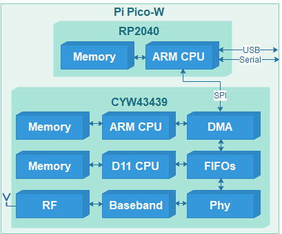
The WiFi chip on the Pi Pico W is the CYW43439, and it contains 2 CPUs, with the attendant memory and peripherals. As a result, initialising the chip is quite complex; for example, it is necessary to load 230 KB of firmware into its memory every time it is powered up. My Picowi project describes the chip initialisation in considerable detail; if you want to learn about the low-level hardware & software interfaces, see part 1 and part 2 of that project.

Once the firmware has been loaded, and the chip CPUs are running, then there are many more commands to configure the interface; these are also sent by the PicoWi software. In the event of an error, there isn’t any corrective action that can be taken, apart from power-cycling the chip, and repeating the whole initialisation process.

Joining a network

The software connects to a WiFi network, that is specified by:

  • SSID. This is the Service Set Identifier, a string broadcast by the Access Point (AP) containing the network name. This is not to be confused with the Basic Service Set Identifier (BSSID); this is the low-level Media Access and Control (MAC) address of the AP, which is not needed.
  • Encryption protocol. This specifies the method that will be used to secure the WiFi transmissions. If the network is ‘open’, then there is no security, and the transmissions can easily be monitored and intercepted. The early security protocols such as WEP (Wired Equivalent Privacy) provide minimal protection, so the more modern WPA (Wi-Fi Protected Access) is generally used, with its successors WPA2 and WPA3.
  • Password. This is the secret encryption key used to encode & decode the transmissions; for WPA it is a string with a length from 8 to 64 characters.

It is not unusual for the network connection attempt to fail, so the code is contained within a loop, and a retry is performed after a suitable delay.

Transmission and reception.

The Mongoose stack is designed to handle a variety of network drivers, that are specified using a single structure with pointers to functions for initialisation, transmission, reception, and network state reporting:

struct mg_tcpip_driver {
  bool (*init)(struct mg_tcpip_if *);
  size_t (*tx)(const void *, size_t, struct mg_tcpip_if *);
  size_t (*rx)(void *buf, size_t len, struct mg_tcpip_if *);
  bool (*up)(struct mg_tcpip_if *);
};

This structure is populated with pointers to the corresponding PicoWi functions:

struct mg_tcpip_driver mg_tcpip_driver_wifi = {
    mg_wifi_init,
    mg_wifi_tx,
    mg_wifi_rx,
    mg_wifi_up };

The transmit & receive functions call the corresponding functions within PicoWi:

// Transmit WiFi data
static size_t mg_wifi_tx(const void *buf, size_t buflen, struct mg_tcpip_if *ifp) 
{
    size_t n = event_net_tx((void *)buf, buflen);
    return  n ? buflen : 0;
}
// Receive WiFi data
static size_t mg_wifi_rx(void *buf, size_t buflen, struct mg_tcpip_if *ifp) 
{
    int n = wifi_poll(buf, buflen);
    return n;
}

It is important to realise that the polling of the WiFi chip isn’t just to receive data, it is also to receive other ‘events’, such as notifications of the network state. Furthermore, Mongoose does not call this function if the network is ‘down’, so there is a risk that the network will be permanently stuck in the ‘down’ state, since the WiFi chip isn’t being polled for events to show the network is ‘up’.

The solution to this problem is to include additional polling in the main loop:

if (!mif.driver->up(0))
    wifi_poll(0, 0);

This polls the WiFi interface if it isn’t reported as ‘up’, so that the change-of-state can be detected. The zero parameters ensure that in the ‘down’ state, any incoming network data is discarded, since nothing useful can arrive until the the network has been joined.

Polling

To those unfamiliar with embedded systems, the extensive use of polling might seem to be counter-productive, resulting in a much slower response to network events – wouldn’t it be quicker to use interrupts?

The answer to this question comes from a deeper understanding of what actually happens within a multi-tasking system. To give an interrupt-driven system a quick response-time, it is important that the interrupt hander doesn’t do much; it has to rapidly save the incoming data, without doing much processing, in order to be ready for the next message. So it will set a semaphore, that will wake up another process that decodes the message format and prepares a response, which is put in a queue for transmission. Then another context-switch will pass control to a transmit routine, to send the response out. It is important to ensure that the hardware isn’t being accessed by 2 routines at the same time, so mutual exclusion (‘mutex’) flags have to be used to guarantee this.

This logic is quite complex, and due to its dynamic nature, is difficult to test & debug; an error can cause the network driver to stall, until an idle-timer expires, and triggers code that tries to resolve the situation.

For this reason, the overall simplicity of single-threaded polled code can appear quite attractive; interrupts can still be used for real-time processing (such as scanning a keypad) whilst the network code keeps running in the background.
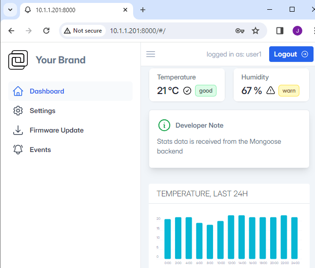
Web server

The Web server (web_server.c) is described in considerable detail in the Mongoose documentation, so there is little I can add. If you log in using one of the given identities, there is a demonstration of various features, but sadly the most interesting (such as Firmware Update) are just dummy functions; extra code is needed to make these operational.

Bulk data transfer

I have previously said that the Web server can provide static (read-only) files from its compiled-in filesystem, and small dynamic files by intercepting the file request callback, and generating the HTML code on-the fly. However there is another use-case; what happens if we want to return a very large file on-the-fly, for example, a picture from a Web camera? Cesanta have provided a ‘huge response’ example, but it involves chopping up the data into smaller sections, and reassembling them on the client using Javascript. I’d like to display the image by simply pointing the browser at its location, so this technique isn’t suitable.

There is an alternative method; just emulate a filesystem containing the file we want to send. When accessing the file, Mongoose starts by issuing a ‘stat’ call to get the data length & timestamp, then follows with an ‘open’ call, multiple ‘read’ calls, and a ‘close’ call. It is easy to intercept these file calls, since they are function pointers in a file API structure:

struct mg_fs {
  int (*st)(const char *path, size_t *size, time_t *mtime);  // stat file
  void (*ls)(const char *path, void (*fn)(const char *, void *), void *);
  void *(*op)(const char *path, int flags);             // Open file
  void (*cl)(void *fd);                                 // Close file
  size_t (*rd)(void *fd, void *buf, size_t len);        // Read file
  size_t (*wr)(void *fd, const void *buf, size_t len);  // Write file
  size_t (*sk)(void *fd, size_t offset);                // Set file position
  bool (*mv)(const char *from, const char *to);         // Rename file
  bool (*rm)(const char *path);                         // Delete file
  bool (*mkd)(const char *path);                        // Create directory
};

Having created our own file handler functions, we can define a new virtual file interface, and specify that it should be used for a specific filename:

// Pointers to file functions
struct mg_fs mg_fs_live = {
    p_stat,  p_list, p_open,   p_close,  p_read,
    p_write, p_seek, p_rename, p_remove, p_mkdir
 };

// In the HTTP connection callback...
struct mg_http_message *hm = (struct mg_http_message *) ev_data;
if (mg_http_match_uri(hm, DATAFILE_NAME)) 
{
    struct mg_http_serve_opts opts = { .fs = &mg_fs_live };
    mg_http_serve_dir(c, hm, &opts);
}

Picomong

This is a port of the mongoose Web server and device dashboard onto the Pi PicoW, using the picowi WiFi driver in place of the conventional lwIP code.

The network details are hard-coded in the firmware, so the file ‘mg_wifi.c’ needs to be edited, to change the default network name (SSID) and password.

It may also be necessary to change the network security setting, the options are:

WHD_SECURITY_WPA_TKIP_PSK,      WHD_SECURITY_WPA_AES_PSK,WHD_SECURITY_WPA_MIXED_PSK,     WHD_SECURITY_WPA2_AES_PSK, WHD_SECURITY_WPA2_TKIP_PSK,     WHD_SECURITY_WPA2_MIXED_PSK,WHD_SECURITY_WPA2_FBT_PSK,      WHD_SECURITY_WPA2_WPA_AES_PSK, WHD_SECURITY_WPA2_WPA_MIXED_PSK,WHD_SECURITY_WPA3_AES,            WHD_SECURITY_WPA3_WPA2_PSK

I have had difficulties with the WPA2_WPA and WPA3_WPA2 settings, so have generally found it best to use PSK with WPA, WPA2 or WPA3.

There is a serial console, with transmit data on pin 1 of the PicoW module, at 115200 baud. When the unit powers up, the on-board LED will flash rapidly, and the console will display something similar to the following:

WiCap v0.26
Using dynamic IP (DHCP)
Detected WiFi chip
Loaded firmware addr 0x0000, len 228914 bytes
Loaded NVRAM addr 0x7FCFC len 768 bytes
MAC address 28:CD:C1:00:C7:D1
Joining network testnet
WiFi wl0: Nov 24 2022 23:10:29 version 7.95.59 (32b4da3 CY) FWID 01-f48003fb
Joined network
IP state: UP
IP state: REQ
IP state: READY, IP: 10.1.1.78, GW: 10.1.1.1

The dynamic IP address will depend on the settings of your network Access Point.

Once the unit has connected to the WiFi network, the LED will flash more slowly (1 Hz); it should respond to network pings, and the Web server will be available on the usual port 80.

The source code is on github here.

Copyright (c) Jeremy P Bentham 2024. Please credit this blog if you use the information or software in it.

PicoWi part 8: UDP server socket

So far I have used a large number of custom functions to configure and control the WiFi networking, but before adding yet more functionality, I need to offer a simpler (and more standard) way of doing all this programming.

When it comes to network programming on Linux or Windows systems, there is only one widely-used Application Programming Interface (API), namely Network Sockets, also known as Internet Sockets. A socket is an endpoint on the network, defined by an IP address & port number; in previous parts, I have used sockets to construct DHCP & DNS clients, and now will use them in a general-purpose programming interface.

UDP & TCP, Client & Server

To recap on the difference between User Datagram Protocol (UDP) & Transmission Control Protocol (TCP), also Client & Server:

  • UDP allows you to send blocks of data across the network, the maximum block size generally being around 1.5 kBytes. There is no synchronisation between sender & receiver, and no error handling, so there is no guarantee that the data will arrive at the destination.
  • TCP starts with an exchange of packets to synchronise the two endpoints, and thereafter the transfer is bidirectional and stream-orientated; it acts like a transparent pipe between the sockets, carrying arbitrary numbers of bytes from one socket to the other. When the transfer is complete, either side can close the connection, but the closure will only be complete when both sides acknowledge it.
  • A client initiates contact with a server, by sending UDP or TCP traffic to a well-known port on that system.
  • A server takes possession of (‘binds to’) a specific UDP or TCP port number, and runs continuously, waiting for a client to initiate contact.

I’m starting with the simplest of these options, namely a UDP server.

UDP server

To create a server socket, it is just necessary to issue a socket() call, followed by bind() to take possession of a specific port, by providing an initialised structure. The same code applies for both Linux, and my RP2040 socket API:

#define PORTNUM  8080    // Server port number
#define MAXLEN   1024    // Maximum data length

int server_sock; 
struct sockaddr_in server_addr, client_addr; 
    
server_sock = socket(AF_INET, SOCK_DGRAM, 0);
if (server_sock < 0)
{ 
    perror("socket creation failed"); 
    return(1); 
} 
memset(&server_addr, 0, sizeof(server_addr)); 
server_addr.sin_family    = AF_INET;
server_addr.sin_addr.s_addr = INADDR_ANY; 
server_addr.sin_port = htons(PORTNUM); 
if (bind(server_sock, (struct sockaddr *)&server_addr, sizeof(server_addr)) < 0) 
{ 
    perror("bind failed"); 
    return(1); 
} 

You may be surprised at the use of 2 structures, namely sockaddr_in, and sockaddr. The former is specific to Internet Protocol, whereas the latter is general-purpose, capable of being used with other network protocols. The structure has to be filled in with the address family (Internet Protocol) the desired IP address (zero for any), and the port number, byte-swapped to big-endian.

The code then enters an endless loop, waiting for a a datagram to be received, printing the data (on the assumption it is text), and returning a text string in response:

printf("UDP server on port %u\n", PORTNUM);
while (1)
{
    memset(&client_addr, 0, sizeof(client_addr)); 
    addrlen = sizeof(client_addr);
    n = recvfrom(server_sock, buffer, MAXLEN-1, 0, 
        (struct sockaddr *)&client_addr, &addrlen);
    if (n > 0)
    {
        buffer[n] = 0; 
        printf("Client %s: %s\n", inet_ntoa(client_addr.sin_addr), buffer); 
        n = sprintf(buffer, "Test %u\n", testnum++);
        sendto(server_sock, buffer, n, MSG_CONFIRM, 
            (struct sockaddr *)&client_addr, addrlen);
    }
}

It may seem strange to set ‘addrlen’ every time we go round the loop; this is for safety, as recvfrom() can potentially modify its value. Also, there is no guarantee that the incoming string is null-terminated, so a null is added at the end of the datagram, just in case.

Blocking

The above code ‘blocks’ on the receive function, that is to say it waits indefinitely until the data arrives, which is standard practice on Linux or Windows sockets – it is sensible when we have a multi-tasking operating system, but inconvenient if we are restricted to a single task, as the CPU can’t run any other code while waiting for incoming data.

There are various ways round this limitation, for example Linux has a ‘select’ function that allows you to poll the interface, checking if any incoming data is available. Alternatively, we can set a timeout on the socket read, for example 0.1 seconds (100,000 microseconds):

struct timeval tv;
tv.tv_sec = 0;
tv.tv_usec = 100000;
setsockopt(server_sock, SOL_SOCKET, SO_RCVTIMEO, &tv, sizeof(tv));

To demonstrate this functionality, we can add a useful feature whereby the LED is flashed every time an access to the server is made; if we set the timeout to 1000 microseconds, then the timeouts give us a convenient millisecond timer. The following code does a rapid flash of the LED until the unit joins the Wifi network, then a quick blink every 2 seconds, plus a flash every time the server is accessed.

sock_set_timeout(server_sock, 1000);
while (1)
{
    memset(&client_addr, 0, sizeof(client_addr)); 
    addrlen = sizeof(client_addr);
    n = recvfrom(server_sock, buffer, MAXLEN, 0, 
        (struct sockaddr *)&client_addr, &addrlen);
    if (n > 0)
    {
        buffer[n] = 0; 
        printf("Client %s: %s\n", inet_ntoa(client_addr.sin_addr), buffer); 
        n = sprintf(buffer, "Test %u\n", testnum++);
        sendto(server_sock, buffer, n, 0, (struct sockaddr *)&client_addr, addrlen);
        msec = 0;
    }
    else
    {
        msec++;
        if (msec == 1)
            wifi_set_led(1);
        else if (msec == 100)
            wifi_set_led(0);
        else if (msec == 200 && !link_check())
            msec = 0;
        else if (msec == 2000)
            msec = 0;
    }
}

Test program

See the introduction for details on how to rebuild and program the udp_socket_server application into the Pico.

The simplest way to test the server is using the netcat application, that can easily be installed on the Raspberry Pi using ‘apt install’; you just need to note the IP address of the Pico as reported on the serial console, and enter it into the netcat command line, e.g. for an address of 192.168.1.240:

echo -n "hello" | nc -4u -w1 192.168.1.240 8080

The server will respond with an incrementing test number, e.g.

Test 1

Alternatively, here is a simple Python client program:

# Simple UDP client example
import time, socket

addr = "192.168.1.240", 8080
data = 'test'

while True:  
    client = socket.socket(socket.AF_INET, socket.SOCK_DGRAM)
    client.settimeout(1)
    client.sendto(str.encode(data), addr)
    print("Tx: " + data);        
    try:
        resp, server = client.recvfrom(1024)
    except socket.timeout:
        resp = None
    print("Rx: " + "timeout" if not resp else resp.decode('utf-8'))
    time.sleep(2)
# EOF

Or in C:

// Simple UDP client for Linux

#include <stdio.h> 
#include <string.h> 
#include <sys/socket.h> 
#include <arpa/inet.h> 
#include <netinet/in.h> 
#include <unistd.h>

#define SERVER_ADDR     "192.168.1.240"
#define SERVER_PORT     8080
#define MAXLEN          1024 

void sock_set_timeout(int sock, int usec);

int main(int argc, char **argv)
{
    int sock, n;
    struct sockaddr_in server_addr;
    char txdata[MAXLEN] = "test", rxdata[MAXLEN];

    sock = socket(AF_INET, SOCK_DGRAM, 0);
    sock_set_timeout(sock, 100000);
    bzero(&server_addr, sizeof(server_addr));
    server_addr.sin_family = AF_INET;
    server_addr.sin_addr.s_addr = INADDR_ANY;
    server_addr.sin_port = htons(SERVER_PORT);
    while (1)
    {
        printf("Tx %s:%u: %s\n", SERVER_ADDR, SERVER_PORT, txdata);
        sendto(sock, txdata, strlen(txdata), 0,
              (struct sockaddr *)&server_addr, sizeof(server_addr));
        n = recvfrom(sock, rxdata, MAXLEN-1, 0, NULL, NULL);
        if (n < 0)
            printf("Rx timeout\n");
        else
        {
            rxdata[n] = 0;
            printf("Rx %s\n", rxdata);
        }
        sleep(2);
    }
    return(0);
}

// Set socket timeout
void sock_set_timeout(int sock, int usec)
{
    struct timeval tv;
    
    tv.tv_sec = usec / 1000000;
    tv.tv_usec = usec % 1000000;
    setsockopt(sock, SOL_SOCKET, SO_RCVTIMEO, &tv, sizeof(tv));
}

Project links
IntroductionProject overview
Part 1Low-level interface; hardware & software
Part 2Initialisation; CYW43xxx chip setup
Part 3IOCTLs and events; driver communication
Part 4Scan and join a network; WPA security
Part 5ARP, IP and ICMP; IP addressing, and ping
Part 6DHCP; fetching IP configuration from server
Part 7DNS; domain name lookup
Part 8UDP server socket
Part 9TCP Web server
Part 10Web camera
Source codeFull C source code

Copyright (c) Jeremy P Bentham 2022. Please credit this blog if you use the information or software in it.

PicoWi part 7: DNS

The Domain Name System (DNS) is the top layer of the 3-layer addressing scheme, as described in the previous part of this blog. To recap:

The Domain Name System translates a Domain Name such as http://www.google.com into an Internet Protocol (IP) address, consisting of 4 decimal numbers 0-255 with ‘.’ separators, e.g. 142.250.187.228.

The Address Resolution Protocol (ARP) translates an IP address into a Medium Access and Control (MAC) address, consisting of 6 hexadecimal values with ‘:’ separators, e.g. 28:CD:C1:00:D9:20

The MAC address is used for all communication within a network, to identify a sender or intended recipient.

In the early days of the Internet there was a simple one-to-one relationship between a domain name and an IP address, so DNS just required a simple lookup on a remote database. Nowadays the name-to-address mapping is much more complex, but we can still take a simple approach, by providing DNS with a name, and it will return an IP address, or several IP addresses if there are some alternatives.

DNS specification

The specifications for DNS, and all other aspects of TCP/IP communication, are in the form of documents called Request For Comments (RFC); DNS is RFC-1034 and RFC-1035. These documents are freely available, and don’t just describe the protocol, but also give background information on the rationale for the design decisions that were made. RFCs are generally very clearly written, with a minimum of jargon, and are well worth a read.

A DNS lookup consists of a single UserDatagram Protocol (UDP) message sent to a server, and a single matching UDP response. UDP is an ‘unreliable’ protocol, so there is no guarantee that a response will be received; if not, the process can just be repeated.

DNS request

The request consists of a fixed-format header, plus variable-format data. The fixed section has just 6 2-byte values:

typedef struct
{
	WORD ident,   // Message identification number
        flags,    // Option flags
	    n_query,  // Number of queries
		n_ans,    // Number of answers
		n_auth,   // Number of authority records
		n_rr;     // Number of additional records
} DNS_HDR;

All values are in ‘network’ byte-order, so are most-significant-byte first. The meaning of the flags can best be described by looking at the decode of a typical request in Wireshark:

Domain Name System (query)
    Transaction ID: 0x1234
    Flags: 0x0100 Standard query
        0... .... .... .... = Response: Message is a query
        .000 0... .... .... = Opcode: Standard query (0)
        .... ..0. .... .... = Truncated: Message is not truncated
        .... ...1 .... .... = Recursion desired: Do query recursively
        .... .... .0.. .... = Z: reserved (0)
        .... .... ...0 .... = Non-authenticated data: Unacceptable
    Questions: 1
    Answer RRs: 0
    Authority RRs: 0
    Additional RRs: 0

This is followed by a variable-length Resource Record (RR) field with the domain name, then 16-bit name type & name class, which normally have a value of 1. Each part of the name is prefixed by a length byte, and the name is terminated by a zero length, e.g.

LEN w w w  LEN r a s p b e r r y p i  LEN o r g  NUL Type Class
03  777777 0b  7261737062657272797069 03  6f7267 00  0001 0001

The code to create the header and data is relatively simple:

// Format DNS request data, given name string
int dns_add_hdr_data(BYTE *buff, char *s) 
{
	BYTE *p, *q;
    DNS_HDR *dhp = (DNS_HDR *)buff;
    int len = sizeof(DNS_HDR);
    static int ident = 1;
    
    memset(dhp, 0, sizeof(DNS_HDR));
    dhp->ident = htons(ident++);
    dhp->flags = htons(0x100);  // Recursion desired
    dhp->n_query = htons(1);
    p = q = &buff[len];
	while (*s)	                // Prefix each part with length byte
	{
		p++;
		while (*s && *s != '.')
			*p++ = (BYTE)*s++;
		*q = (BYTE)(p - q - 1);
		q = p;
    	if (*s)
        	s++;
	}
    *p++ = 0;   // Null terminator
    *p++ = 0;	// Type A (host address)
    *p++ = 1;
    *p++ = 0;	// Class IN
    *p++ = 1;
	return (p - buff);
}

Transmitting this message is just a question of adding on the Ethernet, IP and UDP headers; this is done in a slightly strange order, since the UDP header must include a checksum calculated from the subsequent (DNS) data.

// Transmit DNS request
int dns_tx(MACADDR mac, IPADDR dip, WORD sport, char *s)
{
    char temps[300];
    int oset = 0;
	int len = ip_add_eth(txbuff, mac, my_mac, PCOL_IP);
	int dlen = dns_add_hdr_data(&txbuff[len + sizeof(IPHDR) + sizeof(UDPHDR)], s);
	
	len += ip_add_hdr(&txbuff[len], dip, PUDP, sizeof(UDPHDR) + dlen);
	len += udp_add_hdr_data(&txbuff[len], sport, DNS_SERVER_PORT, 0, dlen);
 	return (ip_tx_eth(txbuff, len));
}

DNS response

The response (if any) will arrive from the WiFi chip as an ‘event’, and it has to go through IP and UDP pre-processing before arriving at the DNS decoder, or any other protocol handler that matches the incoming data. I’ve already established an ‘add_event_handler’ mechanism for distributing events to various handlers, and am using a similar mechanism for distributing incoming UDP traffic, by giving the standard DNS port number:

#define DNS_SERVER_PORT	53
add_event_handler(udp_event_handler);
udp_sock_init(udp_dns_handler, zero_ip, 0, DNS_SERVER_PORT);

// Return number of DNS responses
int dns_num_resps(BYTE *buff, int len)
{
    DNS_HDR *dhp = (DNS_HDR *)&buff[sizeof(ETHERHDR) + sizeof(IPHDR) + sizeof(UDPHDR)];
    return (len > sizeof(ETHERHDR)+sizeof(IPHDR)+sizeof(UDPHDR)+sizeof(DNS_HDR) ?
        htons(dhp->n_ans) : 0);
}

// Handler for UDP DNS response
int udp_dns_handler(UDP_SOCKET *usp)
{    
    char temps[300];
    IPADDR addr;
    int oset = 0;
    
    if (display_mode & DISP_DNS)
    {
        printf("Rx %s: ", dns_hdr_str(temps, usp->data, usp->dlen));
        printf("%s\n", dns_name_str(temps, usp->data, usp->dlen, &oset, 0, 0));
        for (int n = 0; n < dns_num_resps(usp->data, usp->dlen); n++)
            printf("%s\n", dns_name_str(temps, usp->data, usp->dlen, &oset, 0, addr));
    }
    return (1);
}

The response handler just iterates through the responses and prints them out:

Tx DNS 1 query: www.raspberrypi.org type A
Tx UDP 192.168.1.139:1234->192.168.1.254:53 len 37
Rx UDP 192.168.1.254:53->192.168.1.139:1234 len 85
Rx DNS 1 query, 3 resp: www.raspberrypi.org type A
  www.raspberrypi.org type A 104.22.1.43
  www.raspberrypi.org type A 104.22.0.43
  www.raspberrypi.org type A 172.67.36.98

There are 3 responses, but the way they are structured is surprising; this is the binary data:

0040                                 03 77 77 77 0b 72   ...........www.r
0050   61 73 70 62 65 72 72 79 70 69 03 6f 72 67 00 00   aspberrypi.org..
0060   01 00 01 c0 0c 00 01 00 01 00 00 00 df 00 04 68   ...............h
0070   16 01 2b c0 0c 00 01 00 01 00 00 00 df 00 04 68   ..+............h
0080   16 00 2b c0 0c 00 01 00 01 00 00 00 df 00 04 ac   ..+.............
0090   43 24 62                                          C$b

The first entry has the same format as the request, with the domain name http://www.raspberrypi.org having its delimiters replaced by length-bytes. However the subsequent responses have the length byte replaced by the value 0xc0, followed by a value of 0x0c. This 16-bit value is the result of a compression scheme; the two most-significant bits are set to indicate a compressed entry, and the remaining 14 bits are an offset value pointing at the duplicate text (calculated from the start of the DNS header).

The domain name (or compression pointer) is followed by 16-bit type & class words (usually both 1), a 32-bit time-to-live value, then the IP address length and the 4 address bytes.

This makes the decoder quite complex; typically the item most of interest is the IP address, but it is necessary to decode the 3 parts of the name (or the compression pointer) first; see the function dns_name_str() for my version of this.

Misaligned data values

A major issue that arose while debugging the message decoder is the fact that the 16- and 32-bit values in the response may not be aligned on a 2- or 4-byte boundary. This is an issue that is relatively unique to protocol decoding on small embedded systems, but does have a really bad outcome (crashing the CPU) so some explanation is in order. Here is a test program, with a simplified version of the DNS response, just a null-terminated string followed by a 4-byte IP address:

#include <stdio.h>
#include <string.h>

char data[] = {'a', 'b', 'c', 0, 0x11, 0x22, 0x33, 0x44};

typedef unsigned int IPADDR;

int main(int argc, char *argv[])
{
    char *p = &data[strlen(data) + 1];
    IPADDR addr = *(IPADDR *)p;
    printf("%s %X\n", data, addr);
}

When this program is run on the Pico board, or a little-endian Linux system, the result is printed out as expected:

abc 44332211

The program can now be changed so the string is 1 character longer:

char data[] = {'a', 'b', 'c', 'd', 0, 0x11, 0x22, 0x33, 0x44};

The Linux system works as expected, printing out:

abcd 44332211

However the program fails on the Pico, and prints nothing out. If run under a debugger, a ‘hard fault’ trap is reported, with the call stack showing that the problem occurs when the address value is set. This is because the address is no longer on a 4-byte boundary, and the simpler RP2040 processor can’t handle this misaligned transfer, whereas the PC processor can. So it is quite easy to write some code that works fine on a PC, and sometimes fails on the Pico; for example, my early DNS tests used the domain name ‘pool.ntp.org’ and when the response is obtained, all the 16-bit values happen to all be on 2-byte boundaries so the code worked fine; switching to ‘www.raspberrypi.org’ these values became misaligned, so the code failed.

There are various workarounds for this problem, the simplest being not to use casts; my newer code defines the IP address as a byte array, which can be copied byte-by-byte to avoid any misalignment issues. It isn’t sensible to use this approach on 16-bit port values, but these are generally in a byte array and need to be swapped from from big-endian to little-endian, so we can use a byte pointer, e.g.

BYTE *buff;
WORD val = htonsp(buff);

// Convert byte-order in a 'short' variable, given byte pointer
WORD htonsp(BYTE *p)
{
    WORD w = (WORD)(*p++) << 8;
    return(w | *p);
}

Test program

The ‘dns’ program joins a network using the name ‘testname’ and password ‘testpass’ that need to be changed. It uses DHCP to fetch an IP address, and the addresses of a router and DNS server. ARP is then used to resolve the server IP address to a MAC address, then that is used to contact the nameserver, asking to resolve the name http://www.raspberrypi.org, and printing the result.

For more information on compiling and running the code, see the introduction.

Project links
IntroductionProject overview
Part 1Low-level interface; hardware & software
Part 2Initialisation; CYW43xxx chip setup
Part 3IOCTLs and events; driver communication
Part 4Scan and join a network; WPA security
Part 5ARP, IP and ICMP; IP addressing, and ping
Part 6DHCP; fetching IP configuration from server
Part 7DNS; domain name lookup
Part 8UDP server socket
Part 9TCP Web server
Part 10Web camera
Source codeFull C source code

Copyright (c) Jeremy P Bentham 2022. Please credit this blog if you use the information or software in it.