In previous blog posts I used an FTDI module and pure Python code to access the internals of an ARM CPU using the SWD interface. I want to expand this technique to provide a more comprehensive real-time display of the CPU status, but the FTDI interface is quite limiting; what I need is an fast intelligent SWD/JTAG adaptor, with a network interface so I can do both local and remote diagnosis.
Enter the raspberry Pi: a lot of computing power at very low cost, either using the built-in HDMI display output, or running ‘headless’ over a wireless network, providing diagnostic data to a remote display.
Connecting the Pi to the target system could hardly be simpler; 3 wires (clock, data & ground) are sufficient to access data from most CPUs with an SWD interface.


Software-wise, OpenOCD has all the SWD/JTAG features you’ll ever need, accessed through a network interface; installation may be a bit intimidating if you’re not an experienced Linux user, but is really quite easy, as this blog will (hopefully) demonstrate.
What you end up with is a really powerful local/remote debugger for very little money; around $10 US, in the case of the Pi Zero W.
Installing OpenOCD
You need any Raspberry Pi (RPi), versions 0 to 3. The slower boards will have longer boot times & build times but are otherwise fully functional. The OS version I used was ‘Raspbian Stretch with desktop’; the ‘recommended software’ add-ons are not necessary. The total image size on SD card is around 3 GB.
A convenient way to avoid re-typing the instructions below is to enable the Secure Shell (SSH) protocol using the ‘Raspberry Pi Configuration utility’, then run a remote ssh client (e.g. ‘putty’ on Windows) to access the RPi over the network; you can then cut and paste a command line into the ssh window without re-typing. If in doubt as to the IP address of your RPi, hover the cursor over the network icon in the top-right corner, and the address will be shown, e.g. 192.168.1.220 (or run ‘ifconfig’ if in text mode).
It is best to install OpenOCD from source, as the pre-built images often lack important functionality. Installation instructions can be found on many Web sites, for example Adafruit “Programming Microcontrollers using OpenOCD on a Raspberry Pi”. In summary, the steps are:
cd ~
sudo apt-get update
sudo apt-get install git autoconf libtool make pkg-config libusb-1.0-0 libusb-1.0-0-dev
git clone http://openocd.zylin.com/openocd
cd openocd
./bootstrap
./configure --enable-sysfsgpio --enable-bcm2835gpio
make
sudo make install
The ‘make’ step takes approximately an hour on the slower boards, or 15 minutes on the faster.
Configuration files
OpenOCD has a wide variety of options, so generally needs more than one configuration file, to define:
- Debug adaptor (in our case, the RPi)
- Communication method (SWD or JTAG)
- Target CPU.
There are a large number of files in /usr/local/share/openocd/scripts, most notably the ‘interface’ and ‘target’ sub-directories, however there are so many permutations that it is unlikely you’ll find everything you need, so we need to think about creating our own files.
The most important first step is to work out how the RPi will be connected to the target system…
RPi I/O connections
At the time of writing, there are 3 versions of the RPi I/O connector, and 3 different pin-numbering schemes, so it is easy to get confused. The older boards may be considered obsolete, but are still more than adequate for running OpenOCD, so mustn’t be excluded.
The numbering schemes are:
- Connector pin numbers: sequential 1 – 26 or 1 – 40
- GPIO bit numbers (also known as Broadcom or BCM numbers) 0 – 27
- WiringPi numbers, as used in the Python library
I’ll only be using the first 2 of these. The older boards have 26 pins, the newer 40.
Pins 3 & 5 were initially GPIO 0 and 1, but later became GPIO 2 and 3; they are best avoided.
On the 40-way connector GPIO21 has become 27, so should also be avoided. The choice of ground pin is arbitrary; any of them can be used, but I avoid pin 6, as any mis-connection to the supply pins can result in significant damage.
SWD
The SWD connections given in the OpenOCD configuration file ‘raspberrypi2-native.cfg’ are:

The relevant lines in the configuration file are:
# SWD                 swclk swdio
# Header pin numbers: 22    18
bcm2835gpio_swd_nums  25    24

bcm2835gpio_srst_num  18
reset_config srst_only srst_push_pull
In many applications the reset signal is unnecessary – and undesirable, if the objective is to perform non-intrusive monitoring of a running system.
JTAG
JTAG is an older (and more widely available) standard for debugging, that requires 4 wires in the place of 2 for SWD. There is a standard mapping between them (SWCLK is TCK, SWDIO is TMS), but the JTAG connections in the standard OpenOCD configuration file ‘raspberrypi-native.cfg’ use completely different pins:

The relevant lines in the configuration file are:
# JTAG                tck tms tdi tdo
# Header pin numbers: 23  22  19  21
bcm2835gpio_jtag_nums 11  25  10  9

# bcm2835gpio_srst_num 24
# reset_config srst_only srst_push_pull
As standard, the reset definition is commented out.
I’m not a fan of this pinout scheme; I’d like a single setup that covers both SWD and JTAG.
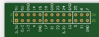
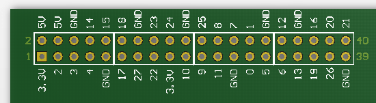
Other pin functions
You might wish to use the RPi for other diagnostic functions, such as monitoring a serial link, so these pins have to be kept free. The following diagram shows the alternative pin functions.

You can use any of the blue or yellow pins for the SWD/JTAG interface, it is just a question as to which other functionality you may be needing.
Combining SWD and JTAG
The compromise I’ve adopted is to preserve the existing SWD arrangement, but move the JTAG pins so one set of connections can serve both SWD & JTAG on either the 26-way or the 40-way connectors – and I’ve also avoided using any of the predefined pins, so there are no conflicts with other functionality.

The relevant section of the configuration file is:
# SWD                swclk swdio
# Header pin numbers 22    18
bcm2835gpio_swd_nums 25    24

# JTAG                tck tms tdi tdo
# Header pin numbers  22  18  16  15
bcm2835gpio_jtag_nums 25  24  23  22
Target system connections
The connection points on the target system will vary from board to board; for a previous demonstration I used a ‘blue pill’ STM32F103 board that has ground, SWD clock & data conveniently on some separate header pins, but the most common standard for JTAG & SWD connections is a 20-way 2-row header, as follows:
JTAG     SWD     20-way pin
Ground   Ground  4, 6, 8, 10, 14, 16, 18, 20
TRST             3
TDI              5
TMS      SWDIO   7
TCK      SWCLK   9
TDO              13
RESET            15
There is generally a keyway on the odd-numbered side of the connector.

Two reset signals are defined: TRST is ‘tap reset’, that is intended to just reset the diagnostic port; the other signal marked RESET (which OpenOCD refers to as SRST or ‘system reset’) should reset all devices, as if a reset button has been pressed. In the experimentation I’ve done, the reset lines haven’t been needed, but this is very processor-specific; sometimes the RESET line has to be used to gain control of the target system.
It is convenient to use ribbon cable for wiring up the interface, especially if the wires follow the resistor colour code:
RPi pin  Colour  20-way pin  JTAG/SWD
9        Brown   20          Ground
12       Red     15          Reset
16       Orange  5           TDI
15       Yellow  13          TDO
18       Green   7           TMS/SWDIO
22       Blue    9           TCK/SWCLK
Or in graphical form…

Interface configuration file
The above examples show how the SWD/JTAG connections are handled, but some more data is needed to fully configure the RPi interface, most notably the I/O base address and clock scaling; this tells OpenOCD where to find the I/O interface, and how to compute its speed.
There are 2 possible values for the I/O base address: the RPi zero and v1 use 0x20000000, and v2+ use 0x3F000000. If you are unsure which value to use, the boards have an excellent feature called Device Tree that documents the current hardware configuration; enter the following command in a console window:
xxd -c 4 -g 4 /proc/device-tree/soc/ranges
The base I/O address is the second value returned, for example:
RPi zero:
00000000: 7e000000  ~...
00000004: 20000000   ...
00000008: 02000000  ....
RPi v3:
00000000: 7e000000 ~...
00000004: 3f000000 ?..
00000008: 02000000 ....
..and so on..
The clock scaling is less critical, since we’re generally aiming for around 1 MHz, which gives quite a bit of leeway in terms of being fast or slow. This is fortunate, because it is difficult to find a definitive explanation of the values that should be used for all hardware & clock settings. My understanding, from reading the source code, is that every I/O read or write instruction is followed by a loop containing NOP (CPU idle) cycles to space out the operations; this number is known as the ‘jtag_delay’, and is calculated by:
(speed_coeff / khz) - speed_offset;
..where speed_coeff & speed_offset are the two scaling parameters, and khz is the desired SWD/JTAG clock speed in kHz (all the values are integers). Obviously the delay is very CPU-dependant; the standard values in the files are:
Rpi zero and v1:
  bcm2835gpio_speed_coeffs 113714 28
RPi v2+:
  bcm2835gpio_speed_coeffs 146203 36
These do seem to give roughly the right answers, and there isn’t any great necessity for the delays to be accurate – when viewed on an oscilloscope, you can see some of the cycles being stretched by an incoming interrupt, so they never will be as accurate as a pure hardware solution.
Adaptor configuration files
Combining all the information above, here are the two adaptor configuration files: rpi1.cfg for RPi zero & v1, and rpi2.cfg for v2+
# rpi1.cfg: OpenOCD interface on RPi zero and v1

# Use RPi GPIO pins
interface bcm2835gpio

# Base address of I/O port
bcm2835gpio_peripheral_base 0x20000000

# Clock scaling
bcm2835gpio_speed_coeffs 113714 28

# SWD                swclk swdio
# Header pin numbers 22    18
bcm2835gpio_swd_nums 25    24

# JTAG                tck tms tdi tdo
# Header pin numbers  22  18  16  15
bcm2835gpio_jtag_nums 25  24  23  22
# rpi2.cfg: OpenOCD interface on RPi v2+

# Use RPi GPIO pins
interface bcm2835gpio

# Base address of I/O port
bcm2835gpio_peripheral_base 0x3F000000

# Clock scaling
bcm2835gpio_speed_coeffs 146203 36

# SWD                swclk swdio
# Header pin numbers 22    18
bcm2835gpio_swd_nums 25    24

# JTAG                tck tms tdi tdo
# Header pin numbers  22  18  16  15
bcm2835gpio_jtag_nums 25  24  23  22
Running OpenOCD
Finally we get to run OpenOCD, but in addition to the adaptor configuration, we need to give some details about the interface & target CPU.
The command line consists of configuration files prefixed by -f, and commands prefixed by -c. In reality, a configuration file is just a series of commands; for example you can select JTAG operation using the command-line option:
openocd -c "transport select jtag"
This is exactly the same as:
openocd -f select_jtag.cfg
where the file ‘select_jtag.cfg’ has the line:
transport select jtag
So we’ll use a mixture of commands and files on our command line. The following example is for an RPi v3 driving an SWD interface into a STM32F103 processor; I’ve used backslash continuation characters at the end of each line to make the commands more readable:
sudo openocd -f rpi2.cfg \
             -c "transport select swd" \
             -c "adapter_khz 1000" \
             -f target/stm32f1x.cfg
Some hardware operations require superuser privileges, hence the use of ‘sudo’. The usual security warnings apply when doing this; you can try without, there will just be a ‘permission denied’ error if it fails.
For a list of supported CPUs, see the files in /usr/local/share/openocd/scripts/target
When OpenOCD runs, with a bit of luck, you’ll see something like:
BCM2835 GPIO nums: swclk = 25, swdio = 24
BCM2835 GPIO config: tck = 25, tms = 24, tdi = 23, tdo = 22
swd
adapter speed: 1000 kHz
adapter speed: 1000 kHz
adapter_nsrst_delay: 100
none separate
cortex_m reset_config sysresetreq
Info : Listening on port 6666 for tcl connections
Info : Listening on port 4444 for telnet connections
Info : BCM2835 GPIO JTAG/SWD bitbang driver
Info : JTAG and SWD modes enabled
Info : clock speed 1001 kHz
Info : SWD DPIDR 0x1ba01477
Info : stm32f1x.cpu: hardware has 6 breakpoints, 4 watchpoints
Info : Listening on port 3333 for gdb connections
If there is a configuration or wiring error, OpenOCD usually (but not always!) returns to the command line, for example if the SWDIO line is disconnected:
BCM2835 GPIO nums: swclk = 25, swdio = 24
BCM2835 GPIO config: tck = 25, tms = 24, tdi = 23, tdo = 22
swd
adapter speed: 1000 kHz
adapter speed: 1000 kHz
adapter_nsrst_delay: 100
none separate
cortex_m reset_config sysresetreq
Info : Listening on port 6666 for tcl connections
Info : Listening on port 4444 for telnet connections
Info : BCM2835 GPIO JTAG/SWD bitbang driver
Info : JTAG and SWD modes enabled
Info : clock speed 1001 kHz
Info : SWD DPIDR 0x02192468

..and then OpenOCD terminates back to the command line..
The clue is in the SWD Data Port ID Register (DPIDR) value. According to the datasheet for the STM32F103 CPU, this should be 1BA01477. With a data line fault, every time OpenOCD runs, a different value is returned, e.g. 0x00e65468, 0x02192468, 0x00433468 and so on; the software is just picking up noise on the data line.
A disconnected clock line is harder to diagnose, as OpenOCD just terminates after the ‘clock speed’ report, with no error indication. Try using the -d option to invoke a debug display, and you’ll see lines like
JUNK DP read reg 0 = ffffffff
which suggests that all is not well in the hardware interface.
Another thing to try in the event of a failure is adding or removing a reset line, and changing its configuration entries; if there is a reset problem you’ll probably see the DPIDR value reported correctly, but other functions may not work.
What now?
Having just written 2100 words and drawn 8 diagrams, I’m going to take a short break. However, first I ought to give some indication as to how you control this OpenOCD setup.
The sign-on text mentions a telnet interface on port 4444, so we can use that; the commands highlighted in bold:
sudo apt-get install telnet  # ..if not already installed

telnet localhost 4444
Trying ::1...
Trying 127.0.0.1...
Connected to localhost.
Escape character is '^]'.
Open On-Chip Debugger
>
As standard, this interface only works when telnet is running locally on the Raspberry Pi. To open it up to a wider network, add the command ‘bindto 0.0.0.0’ to the configuration. However, this option comes with a major security warning; think very carefully before making the system accessible to everyone on the network.
Refer to the OpenOCD documentation for information on the large number of commands that can be used over telnet, for example displaying memory using ‘mdw’ or halting the processor using ‘halt’. When finished, close the telnet link with ‘exit’.
Open-source development toolchain
To learn more about the way OpenOCD can be used with GCC and GDB to program & debug ARM target systems, take a look at this post.
Copyright (c) Jeremy P Bentham 2019. Please credit iosoft.blog if you use the information or software in here.

One of the best “How To” I’ve seen. I used it to get going with ESP32. If going with ESP32 you have to use Espressif’s own version of OpenOCD:
git clone –recursive https://github.com/espressif/openocd-esp32.git
LikeLike
Thanks very much for the comment; I intended to use the ESP32 in a WiFi project, but was a bit concerned as to the data throughput: I need a fast network interface, and got the impression that the ESP32 could be a bit erratic & slow. So maybe I’ll try a module with a Broadcom/Cypress chip such as CYW43362 instead.
LikeLike
For whatever reason when I compile openocd on my rasbperry running manjaro arm it gets built without bcm2835gpio driver unless I also suply “–build=arm-linux –disable-parport-ppdev” parameters to configure command.
LikeLike
Thanks for the hint; I have no experience of Manjaro, but I guess they are using some of the I/O pins as a legacy parallel port, and this clashes with the pins I’m using for SWD/JTAG.
LikeLike