There is a newer version of this utility, that runs on Windows or Linux, and uses a USB debug adaptor in place of the direct I/O, see the PicoReg2 project here.

The Raspberry Pi Pico CPU (RP2040) has a remarkably complex set of peripherals, and this is reflected in the very large number of control registers (1,116).
To debug a C or Python application, it can be very helpful to know the values in these registers; instead of adding ‘print’ calls, or using a heavyweight debugger, you can use a 3-wire connection between the Pico and a Raspberry Pi, and view the state of any register without modifying or disrupting the software. This magic is achieved using the Single Wire Debug (SWD) interface; it is mainly used for reprogramming the Flash memory of the Pico, but can do a lot more – it acts as a transparent window into the I/O subsystems, that is completely independent of the CPU.
This capability can be accessed using software tools such as OpenOCD, GDB, and Eclipse, but I wanted to create something much simpler, and easier to use. The end-result is PicoReg, which is a pure-Python program that runs on any Raspberry Pi. In addition to the SWD interface, it can access the standard System View Description (SVD) file, to give a description of every register in considerable detail.
The end-result is a simple-to-use software tool that gives a valuable insight into the inner workings of the Pico.
Installation
Hardware

Only 3 wires are needed; a ground connection, SWCLK and SWDIO.
Any I/O pins on the Pi could be used; for ease of identification, I’ve chosen BCM pin numbers 20 and 21. These should be connected to the SWCLK and SWDIO pins on the edge of the Pico; keep the wires as short as possible, ideally a 150 mm (6 inches) or less.

The pins are defined at the top of picoreg_gpio.py, so can easily be changed to any others, but you need to be sure there is no conflict with other device drivers, such as serial, SPI etc.
# Clock and data BCM pin numbers
CLK_PIN         = 20
DAT_PIN         = 21
The Pico will need to be powered as normal, for example using a 5V supply into the USB socket, or if the Pico USB interface is not connected, linking the the 5V pin on the Pi to the VSYS pin on the Pico.
Software
There are 2 Python files, and one database file:
- picoreg_gpio.py. The low-level interface code, with a very simple command-line interface.
- picoreg_qt.py. A PyQt application with full GUI, that uses picoreg_gpio as a low-level interface.
- rp2040.svd. The System View Description file provided by the Raspberry Pi organisation, that describes all the peripheral registers in XML format
The GUI translates register names (such as TIMER.ALARM3) into physical addresses (such as 0x4005401c) using the SVD file; if it is missing, the GUI won’t work. The software performs best on a Pi 3 or 4; it will work on earlier devices, but is a bit slower.
The files can be found on github here; copy them to any convenient directory, then install PyQt5 on the Pi. The current version at the time of writing is 5.11.3:
sudo apt update
sudo apt install python3-pyqt5
That is all you need to do!
Running the GUI
Start the GUI from a console:
python3 picoreg_qt.py
The application will respond “Loading rp2040.vsd”, then after a short delay, will show the GUI. You may also see some warning messages from PyQt, but these are harmless.

The controls are:
- Core number. The Pico is a 2-core device, and this allows you to select core 0 or 1. There is no practical difference when using Picoreg to look at I/O, since the peripheral registers are common to both cores.
- Verbose. This allows you to see the SWD messages that Picoreg is sending, and the responses obtained; useful when there are problems with the link.
- Connect. This starts communication with the Pico, and verifies the identity of the RP2040 CPU. When the link is broken, it is necessary to re-connect before doing any register accesses.
- Single. When connected, this button takes a single reading from the highlighted register.
- Run. When connected, this button starts a continuous cycle of reading from the highlighted register, at 5 readings per second.
Note that this initial display is not Raspberry-Pi-specific; it will run on any PC, even under Windows. This allows you to browse the register database on any convenient machine, though the low-level I/O code is Pi-specific (using the RPI.GPIO module), so the SWD code only runs on a Pi.
The upper display is a tree structure, containing the peripherals, registers, and fields within the registers. By default it is alphabetically sorted, click on the ‘base’ header, to sort by address. The lower display shows general information, and a description of the selected register.
If the SVD database file is damaged or missing, Picoreg will report a syntax error; check that the file is in the same directory as picroreg_qy.py, and restart.
Click on ‘connect’ and if all is well, the following will be displayed.
SWD connection restart
DPIDR 0x0bc12477
The Debug Port Identification Register value shows that Picoreg connection has succeeded. The software makes 3 attempts to do this, and if unsuccessful, the most likely cause is incorrect wiring, or the Pico board not being powered up.
You can navigate around the register display using mouse (single or double-click) or keyboard, as is usual for such tree displays.
If you have a new un-programmed Pico, try navigating to the TIMER.TIMELR register, and hit ‘Run’.
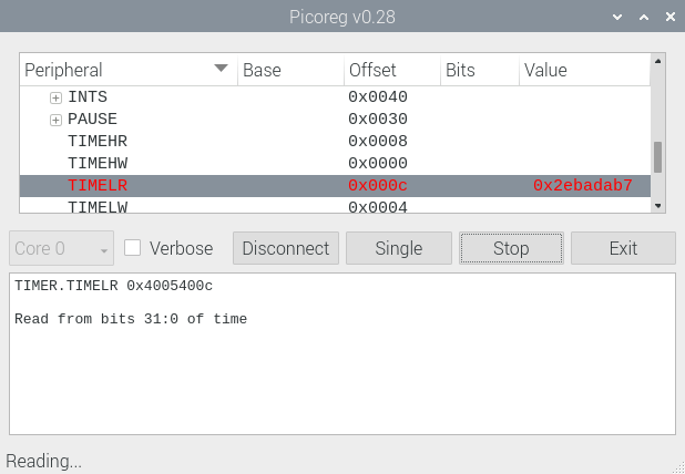
You should see a rapidly-changing display of the current timer value; you can then move the cursor to other registers, whilst the data collection is still running; the register value under the cursor will be updated, while previously-accessed register values are static. There is a flashing indication in the bottom-left corner of the window to show that data collection is running.
Debugging an application
Load the following MicroPython application onto the Pico
# Simple test of O/P and ADC
from machine import Pin, Timer, ADC
led = Pin(25, Pin.OUT)
temperature = ADC(4)
timer = Timer()

def blink(timer):
    led.toggle()
    print(temperature.read_u16())

timer.init(freq=2, mode=Timer.PERIODIC, callback=blink)
The on-board LED will flash at 1 Hz, and the console will report the ADC value on the temperature channel.
You can use PicoReg to display the raw ADC value, in the ADC.RESULT register:

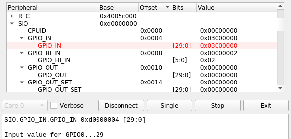
The state of the I/O pins is in the SIO.SPIO_IN register:
You can even see activity on the USB link, as the data pins toggle high and low:

Potential issues
Styling
This proved to be a surprising headache; it has been remarkably difficult to get consistent styling. Some of the screenshots were taken on a Pi 3 running Qt 5.11.3, remote-controlled from a PC, using SSH:
export DISPLAY=:0.0
python3 picoreg_qt.py
The others are run directly from a Pi console, and look quite different (and not as nice, in my opinion).
I’ve already used some very limited styling to customise the tree display:
TREE_STYLE    = ("QTreeView{selection-color:#FF0000;} " +
                 "QTreeView{selection-background-color:#FFEEEE;} ")

self.tree.setStyleSheet(TREE_STYLE)
However, after many hours of experimentation, I still haven’t found a way of getting a consistent appearance – feel free to tackle this problem yourself!
Errors
PicoReg uses pure-python code; on the plus side, you get the convenience of not having to install any device-drivers, but on the minus-side the SWD timing is a bit unpredictable, and can be stretched out when a higher-priority task takes control of the CPU. This is particularly noticeable when resizing or repositioning the display window; the software makes 3 attempts to re-establish connection with the Pico, but may time out and disconnect.
This behaviour is harmless, and it is only necessary to click the ‘Connect’ button to re-establish communications.
Console interface
If there are problems running the graphical interface, the low-level drivers in can be run directly from the command line:
python3 picoreg_gpio.py [options] [address]
    options: -v Verbose mode
             -r Repeated access
    address: hexadecimal address to be monitored
The default address to be monitored is the GPIO input 0xD0000004. The low-level driver can’t access the SVD database, so the address has to be specified in hexadecimal, e.g. to display the timer value:
python3 picoreg_gpio.py -r 0x4005400c
SWD connection restart
DPIDR 0x0bc12477
0x4005400c: 0xefa1b0d0
0x4005400c: 0xefa26046
0x4005400c: 0xefa30fc8
0x4005400c: 0xefa3bf32
0x4005400c: 0xefa46ec3
..and so on, use ctrl-C to exit
How it works
The SWD link has 2 wires: a clock line, and a bi-directional data line. All transactions are initiated by the Pi, the Pico only transmits on the data line when requested. The data is sent LSB (Least Significant Bit) first.
Each message starts with an 8-bit header, and the Pico responds with a 3-bit acknowledgement; if this is OK (bit value 1, 0, 0) then a 32-bit data value is transferred (sent or received), followed by a parity bit.
As there is only one data line, the Pi has to switch its direction from transmit to receive to get the acknowledgement, and then switch back to transmit (if it is a write cycle) or allow the Pico to send 32 bits of data (if it is a read cycle).
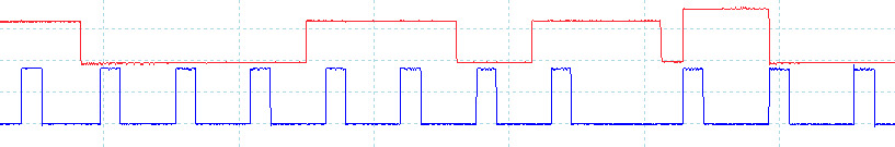
An extra complication that isn’t emphasised in the ARM documentation, is that the active edge changes as well; the Pi sends data that is stable on the rising clock edge, but the Pico data is stable on the falling clock edge, as shown in the following oscilloscope trace. [The response from the Pico has been amplified for clarity; normally it is the same magnitude as the outgoing signal from the Pi.]

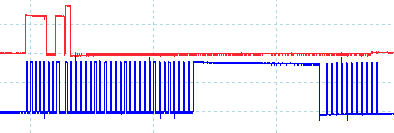
The unusual elements of this protocol make it quite tricky to implement in pure Python, and I must admit the above trace wasn’t generated by my code; it comes from OpenOCD, with an FTDI USB adaptor. The following trace is generated by my code, the frequency is a bit lower (approximately 100 kHz) and is less symmetrical.
The asymmetric waveform isn’t a problem, but a disadvantage of the pure-Python approach is that there are occasions when the CPU is performing other tasks, and it stop driving the SWD interface.
The trace below shows a 300 microsecond pause in the middle of a transfer, and unsurprisingly the Pico doesn’t like this, and returns an error response. Occasional errors like this aren’t a problem, as they are easily handled by the retry mechanism in the PicoReg code.
Error handling
When there is an error, the Pico completely stops communicating over the SWD interface, and ignores all subsequent commands; it is necessary to reset the SWD interface, to re-establish communication.
The reset process is deliberately quite complex, involving the transmission of:
- 8 all-1 bits (FF hex)
- 16 bytes of a specific polynomial
- 4 all-0 bits (0 hex)
- 1 byte to activate the SW-DP interface
- At least 50 all-1 bits
If there are any errors in the process, the Pico will not respond, which makes debugging a bit tricky. Once reset, the connection has to re-established by, transmitting the ID of the core to be accessed; the RP2040 processor has two cores, that are selected using a value of 0x01002927 or 0x11002927. When browsing the peripheral registers, it doesn’t matter which core is selected; the results will be the same.
Higher-level protocol
You might think that, having established contact with the CPU, it would be easy to read the register values, but in reality the interface has several extra levels of complication; some of these I’ve already documented in a previous project, but if you are seeking more information, you really need to read the Arm Debug Interface Architecture Specification (ADI). At the time of writing the latest version (v6.0) is available here.
Copyright (c) Jeremy P Bentham 2021. Please credit this blog if you use the information or software in it.

Hi Jeremy – well researched and explained! It looks like you need a bit of C or assembler to do the SWD interfacing, or perhaps another Pico?
Tony
LikeLike
Yes, at some stage I’ll modify the code to use a second Pico as the SWD interface, but for the time being the pure-Python approach works remarkably well; there is little point gathering data at very high speed, only to display it at a speed suitable for human comprehension – very slow!
LikeLike