Zerowi bare-metal WiFi driver part 2: SDIO

Hardware

I’m starting this project with the Raspberry Pi ZeroW, which uses the Cypress WiFi chip CYW43438. It interfaces to the ARM processor using Secure Digital I/O (SDIO), which consists of the following signals:

  • Clock (1 line, O/P from CPU)
  • Command (1 line, I/O)
  • Data (4 lines, I/O)

Later in this blog, I’ll be describing what these pins do, in case you are a newcomer to the strange world of SDIO.

The I/O bit numbers are defined in the DeviceTree file for the board:

sdio_pins {
    brcm,pins = <0x00000022 0x00000023 0x00000024 0x00000025 0x00000026 0x00000027>;
    brcm,function = <0x00000007>;
    brcm,pull = <0x00000000 0x00000002 0x00000002 0x00000002 0x00000002 0x00000002>;
    phandle = <0x00000019>;
};

The ‘pull’ settings show that pullup resistors are enabled for pin 23 to 27 hex (GPIO35 to 39), and an initial guess would be that these pins are the command and data, while 22 hex (GPIO34) is the clock.

The datasheet mentions a power-on signal, and a quick trawl on the Web suggests that this could be GPIO41, which must be high to power up the WiFi interface. There is also mention of a low-speed (32 kHz) clock that may be needed when waking up the chip from low-power mode; it turns out this is on GPIO43. This can be verified by dumping the I/O configuration registers when the WiFi interface is running:

  20300000: 0013D660 00017030 A5040030 353A0002 00001000 00000000 00000000 00000000
  20300020: 00000000 01FF0000 00000F02 000E0207 00000000 00FF0133 00FF0133 00000000

Each pin has a 3-bit mode value, that shows whether it being used for simple input, output, or is connected to an internal peripheral (ALT0 – 5). The values above can be decoded by referring to the ‘BCM2835 ARM Peripherals’ data sheet, but an easier way is to use the ‘pigs’ front-end for the PIGPIO library, thus:

sudo pigpiod   [load PIGPIO daemon]
pigs mg 34     [get mode of GPIO pin 34]
7              [returned value 7: pin is ALT3]
pigs mg 43     [get mode of GPIO pin 43]
4              [returned value 4: pin is ALT0]

Pins 34 to 39 are all set to ALT3, which is unhelpfully labelled in the BCM2835 datasheet as ‘reserved’; in reality this means they are connected to the (undocumented) Arasan SD controller. GPIO43 is configured as ALT0, which is the clock source GPCLK2, configured for 32.768 kHz.

Attaching a logic analyser

To understand what the Linux driver is doing, I need to attach a logic analyser to the SDIO bus. This isn’t easy on most boards; the interface runs very fast (up to 50 MHz) so the only means of attachment is by soldering onto extremely small surface-mount components, that can easily be damaged.

However, the Pi Zerow has some interesting pads on the underside.

SDIO pads

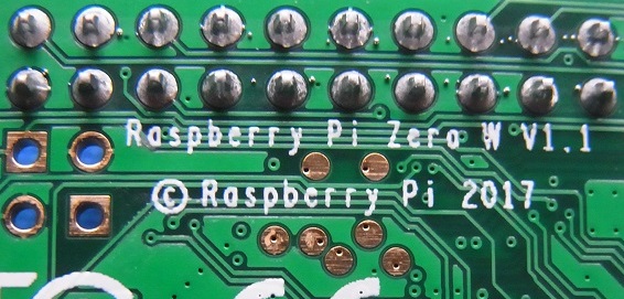
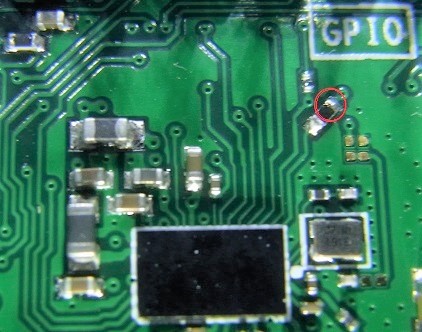
Those 7 gold circles are clearly attached to some internal signals, since they have conductive holes (known as ‘vias’) to tracks on other layers. Also, they’re in the right area for the SDIO interface, and it is possible they’re needed for testing the WiFi/ Bluetooth interface after the PCB is assembled. Monitoring these signals with WiFi running proved that they do have almost all of the SDIO signals, aside from the most important one: the clock. Further probing suggested that the only way to pick up that signal is on the other side of the board at a resistor, but connecting to this point is tricky; you need good surface-mount soldering skills to avoid damaging the board.

SDIO clock connection

The main problem with the logic analyser interface is the sheer volume of data that’ll be accumulated. The boot process takes around a minute, with sporadic activity on the SDIO interface; catching all that, with a data rate of 50 MHz, would require a very complicated and/or expensive setup. Fortunately, the Raspberry Pi has an ‘overclocking’ setting in the boot file config.txt, which sets the clock rate to be used when the OS requests 50 MHz. This doesn’t just speed up the interface; a value of 1 or 2 MHz can be used to slow it right down, e.g.

# Add to /boot/config.txt:
dtparam=sdio_overclock=2

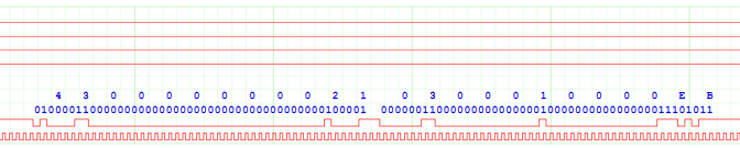
This allows a lower-cost analyser to be used (see part 1 of this blog for details) – and surprisingly, the change doesn’t make a lot of difference to the boot-time, since there are long pauses in SDIO activity, where the OS is doing other things. This can be seen by zooming the analyser display out to the maximum, showing 50 seconds of data:

SDIO activity during Linux boot

The bottom trace is the clock, the next is the command (CMD) line, then there are the 4 data lines. Despite the long periods with no activity, there is a lot going on: over 2,200 commands and 13,000 data blocks are being exchanged between the CPU and the WiFi chip.

SDIO protocol

If, like me, you have some experience of the Serial Peripheral Interface (SPI), you may expect SDIO to be similar, in that it uses a clock line to synchronise the sender & receiver; the rising edge of the clock indicates that the data is stable, and can be read by the receiver.

However, there are a few key differences:

  • Bi-directional. All the lines, apart from the clock, are bi-directional; either side can drive them.
  • Command and data lines. There are separate lines for commands and data, and the 4 data lines act as a 4-bit parallel bus.
  • Start & end bits. Instead of the SPI chip-select, the data and command lines idle high, then go low to signal the start of a transfer; this is referred to as a ‘start bit’, and is a single bit-time with a value of zero. At the end of the transfer there is a single bit with a value of 1, an ‘end bit’.
  • Format. The format of SDIO commands and responses is standardised, with specific meaning to the transferred bytes.

It is well worth reading the SDIO specification; at the time of writing, the latest version that is available from the SD Association is “SD Specifications Part E1, SDIO Simplified Specification Version 3.00”. For a few of the commands you need to refer back to the “SD Specifications Part 1 Physical Layer Simplified Specification”, for example:

SD command and response

This is SD command 3 (generally abbreviated to CMD3) and response 6 (R6) from the target (WiFi chip). Both are specified at being 48 bits long, and you can see they begin with a 0 start-bit, and finish with a 1 end-bit. Between the two, the command line is briefly idle. It is a bit confusing that the reply to a command 3 is not a response 3; this is because there are a lot of commands (over 50) but many of them share the same response format, so only 7 possible responses have been defined.

The most common commands used in the SDIO interface are CMD52 and 53. Command 52 is used to read or write a single 8-bit value, while CMD53 transfers blocks of data, either singly or in batches. The following trace shows command 53 reading a single block of 4 data bytes; the command and response look similar to command 52, but there is also activity on the data lines, starting with a 4-bit value of zero, and ending with F hex.

SDIO command 53

SDIO interface code

In the absence of the necessary documentation, writing code for the ‘Arasan’ SD controller on the Raspberry Pi would be quite fraught, so I decided to use direct control (‘bit-bashing’ or ‘bit-banging’) of the I/O lines. The more experienced among you might be thinking this is a really bad idea, as it can be very CPU-intensive and slow, but I believe that the end-result (for example, booting the WiFi chip from scratch in 1 second) vindicates my decision – and if you want to use the controller, you can modify my code to do so.

The bit-patterns within the SDIO commands and responses are quite complex, and the code I’ve seen makes heavy use of bit-masking and shifting to combine the individual values into a single message. I’m not a fan of this approach, and prefer to use C language bitfields. For example, CMD52 has the following fields in the 6-byte message:

Start:             1 bit  (always 0)
Direction:         1 bit  (1 for command, 0 for response)
Command index:     6 bits (52 decimal for command 52)
R/W flag:          1 bit  (0 for read, 1 for write)
Function number:   3 bits (select the bus, backplane or radio interface)
RAW flag:          1 bit  (1 to read back result of write)
Unused:            1 bit
Register address: 17 bits (128K address space)
Unused:            1 bit
Data value:        8 bits (byte to be written, unused if read cycle)
CRC:               7 bits (cyclic redundancy check)
End:               1 bit  (always 1)

You’ll see that the values don’t all line up on convenient 8-bit boundaries; furthermore the data sheet defines the values with most-significant value first, whereas standard C structures have least-significant first.

My solution is to use macros to reverse the order of bits in the byte, so the command structure looks similar to the specification. These are used to create structures for the commands and responses, which are combined in a union.

#define BITF1(typ, a)             typ a
#define BITF2(typ, a, b)          typ b, a
#define BITF3(typ, a, b, c)       typ c, b, a
..and so on..

typedef struct
{
    BITF3(uint8_t,  start:1, cmd:1,   num:6);
    BITF5(uint8_t,  wr:1,    func:3,  raw:1, x1:1, addrh:2);
    BITF1(uint8_t,  addrm);
    BITF2(uint8_t,  addrl:7, x2:1);
    BITF1(uint8_t,  data);
    BITF2(uint8_t,  crc:7,   stop:1);
} SDIO_CMD52_STRUCT;

typedef union 
{
    SDIO_CMD52_STRUCT   cmd52;
    SDIO_RSP52_STRUCT   rsp52;
    SDIO_CMD53_STRUCT   cmd53;
    uint8_t             data[MSG_BYTES+2];
} SDIO_MSG;

The code to split the 17-bit address into 3 bytes is still a bit messy, but the structure definition does simplify the process of creating a command:

// Send SDIO command 52, get response, return 0 if none
int sdio_cmd52(int func, int addr, uint8_t data, int wr, int raw, SDIO_MSG *rsp)
{
    SDIO_MSG cmd={.cmd52 = {.start=0, .cmd=1, .num=52,
        .wr=wr, .func=func, .raw=raw, .x1=0, .addrh=(uint8_t)(addr>>15 & 3),
        .addrm=(uint8_t)(addr>>7 & 0xff), .addrl=(uint8_t)(addr&0x7f), .x2=0,
        .data=data, .crc=0, .stop=1}};

    return(sdio_cmd_rsp(&cmd, rsp));
}

For speed, the CRC is created using a byte-wide lookup table in RAM, which is computed on startup:

#define CRC7_POLY    (uint8_t)(0b10001001 << 1)

uint8_t crc7_table[256];

// Initialise CRC7 calculator
void crc7_init(void)
{
    for (int i=0; i<256; i++)
        crc7_table[i] = crc7_byte(i);
}

// Calculate 7-bit CRC of byte, return as bits 1-7
uint8_t crc7_byte(uint8_t b)
{
    uint16_t n, w=b;

    for (n=0; n<8; n++)
    {
        w <<= 1;
        if (w & 0x100)
            w ^= CRC7_POLY;
    }
    return((uint8_t)w);
}

// Calculate 7-bit CRC of data bytes, with l.s.bit as stop bit
uint8_t crc7_data(uint8_t *data, int n)
{
    uint8_t crc=0;

    while (n--)
        crc = crc7_table[crc ^ *data++];
    return(crc | 1);
}

Data CRC

The data transfer includes a CRC for every line, for example this is the transfer of the 4 bytes A6, A9, 41, and 15 hex.

Command 53 data read

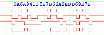
A total of 12 bytes are transferred, because each data line has an added 16-bit CRC. This was a bit of a headache, since splitting the 4-bit data into individual 1-bit values for CRC calculation would considerably slow down the command generation & checking. Fortunately there is a easy way to calculate & check the CRC for each line, while still keeping the 4 values together. This comes from the realisation that the exclusive-or operation in the CRC doesn’t care what order the bits are in; we can rearrange the bits to match our data. So we can compute all 4 CRCs using a single 64-bit value:

Bit 0: bit 0 of 1st CRC
Bit 1: bit 0 of 2nd CRC
Bit 2: bit 0 of 3rd CRC
Bit 3: bit 0 of 4th CRC
Bit 4: bit 1 of 1st CRC
..and so on, up to..
Bit 63: bit 15 of 4th CRC

Once they have been computed, the 4 CRCs are transmitted by just shifting out the next 4 bits of the 64-bit value. To speed up the calculation, a 4-bit lookup table is initialised on startup:

#define CRC16R_POLY  (1<<(15-0) | 1<<(15-5) | 1<<(15-12))

uint64_t qcrc16r_poly, qcrc16r_table[16];

// Initialise bit-reversed CRC16 lookup table for 4-bit values
void qcrc16r_init(void)
{
    qcrc16r_poly = quadval(CRC16R_POLY);
    for (int i=0; i<(1<<SD_DATA_PINS); i++)
        qcrc16r_table[i]  = (i & 8 ? qcrc16r_poly<<3 : 0) |
                            (i & 4 ? qcrc16r_poly<<2 : 0) |
                            (i & 2 ? qcrc16r_poly<<1 : 0) |
                            (i & 1 ? qcrc16r_poly<<0 : 0);
}

// Spread a 16-bit value to occupy 64 bits
uint64_t quadval(uint16_t val)
{
    uint64_t ret=0;

    for (int i=0; i<16; i++)
        ret |= val & (1<<i) ? 1LL<<(i*4) : 0;
    return(ret);
}

Now when transmitting, the 64-bit (i.e. 4 x 16-bit) CRC is updated with every 4-bit value:

uint64_t qcrc=0;

// For each 4-bit value 'd':
qcrc = (qcrc >> 4) ^ qcrc16r_table[(d ^ (uint8_t)qcrc) & 0xf];

After the data has been sent, the CRC values are transmitted:

for (n=0; n<16; n++)
{
    output((uint8_t)qcrc & 0xf);
    qcrc >>= 4;
}

Bulk transfers

Command 53 can be used to transfer a single block (where the block size is specified in the command) or multiple blocks (where the block size has previously been set, and the number of blocks is specified in the command).

If the CPU is sending a single command, then writing multiple blocks to the WiFi chip, how does it check that the blocks are being received and processed OK? The answer is that when writing blocks, the recipient generates a brief acknowledgement back. Here is an example of a CMD53 write.

Command 53 write

It is a bit difficult to see what is going on; the command and response are similar to all the others, but then (after a surprisingly long pause) the data is transferred from the CPU to the WiFi chip. Zooming in on that data:

Command 53 write data

4 bytes with the values 3, 0, 0, 0, are being transferred, then 8 bytes of CRC. However, after that, the recipient acknowledges the received data by driving the least-significant data line with a bit value of 00101000 00111111 (28 3F hex). To be honest, I haven’t been able to find a proper description of these bits; I assume there is a single byte value, then the recipient holds the line low until it has finished processing, but the meaning of the byte bits isn’t at all clear. So for the time being, my code reads in the byte value, then waits for the line to go high, effectively treating it as a ‘busy bit’.

Clock polarity

A small but significant detail is the relationship between the data changes and the clock edges – when is the data stable so it can be read? I previously suggested that the data is read on the positive clock-edge, but look at this trace showing the transition between the command and the response:

Command and response clocking

For the command, the data changes on the negative-going clock edge, so can be read on the positive-going edge. The response appears to be the opposite way around, with the data changing on the positive-going edge – what is going on?

The answer is that the WiFi chip has been set to ‘SDIO High-Speed’ mode; the data changes very shortly after the positive-going edge of the clock, so as to enable fast transfers. The timing is described in the chip data sheet if you want to know the details, but the end result is that the logic analyser isn’t fast enough to capture the gap between clock & data changes, so the software that analyses the logic traces has to use the last state before the clock goes high.

Bit bashing

The bit-bash (or bit-bang) code was quite difficult to write; it has to toggle the clock line, feed out the single-bit command, then get the response whilst simultaneously sending or receiving the 4-bit data. Also, although the examples above show the data being shorter than the response, in reality it can be considerably longer, up to 512 bytes, so will finish long after the activity on the command line. Then there is the issue of the acknowledgements of block data writes, and the need for a timeout in case the chip goes unresponsive…

There is no point describing the code here; if you are interested, take a look at the source. In theory, it’d be a good idea to replace it with a driver for the Arasan SD controller, but I’m not sure there would be a large speed gain – the Linux driver seems to spend a lot of time idle, waiting for the SD controller to complete a task. Also the bit-bashing code is more universal: it shouldn’t be too difficult to port it to other processors such as the STM32, which is frequently paired with the Cypress chip in a standalone module.

SPI interface

For completeness, I need to mention that according to the data sheet, the WiFi chip has a Serial Peripheral Interface (SPI), that can be used instead of SDIO. This is enabled by sending a reset command to the chip, while certain I/O lines are held in specific states.

I originally thought this interface would be easier to use than SDIO, but all my attempts to get it working failed. Also, the SPI connections don’t seem to line up with the SPI master in the BCM2835, so the interface would have to be bit-bashed, which would be really slow as the data bus is only 1-bit-wide. So I abandoned SPI, and focused exclusively on SDIO.

[Overview] [Previous part] [Next part]

Copyright (c) Jeremy P Bentham 2020. Please credit this blog if you use the information or software in it.

Zerowi bare-metal WiFi driver part 1: resources

The WiFi chips on the Raspberry Pi boards are from the Broadcom BCM43xxx range, which has been taken over by Cypress, and renamed CYW43xxx. The Pi ZeroW uses the CYW43438, the PDF data sheet is here.

The obvious starting point for creating a new driver is the existing Linux driver, known as ‘Broadcom Full MAC’, or BRCMFMAC. The source is available here.

A more recent driver is included in the Cypress WICED development system. This is based on Eclipse, and is very comprehensive, covering a wide range of wireless chips and functionality.

A more compact version of the code is available as the Cypress Wifi Host Driver, which is intended for integration in real-time systems.

Another (highly unusual) WiFi driver is available for the Plan9 operating system, contained within a single file ether4330.c. This has a large number of unconventional operating-system dependencies, and would require significant modifications to run on a bare-metal platform, but is interesting as the author has succeeded in creating some remarkably compact code.

To see an example of an SPI interface with a CYW43439, take a look at my Zerowi standalone driver for the Raspberry Pi Pico W here.

It is great to have such a range of source-code available, but in practice it has been of minimal use in this project; even the simplest versions are exceedingly complex, with hidden dependencies & timing issues, so rather than simplifying existing code, I have written all the code from scratch.

Documentation on the Broadcom/Cypress chips is very limited; the data sheet gives minimal information about the chip internals. There is a programming manual, but that only available from Cypress under a confidentiality agreement. I haven’t had access to that document, as it would place severe restrictions on what I can write in this blog. So I have just used freely-available information, logic analysis, and a lot of trial-and-error.

With regard to a logic analyser, the requirements for this project are a bit demanding. The Raspberry Pi ZeroW takes nearly a minute to boot, so a recording of the hardware activity will be quite long, overflowing the memory of most logic analysers. So it is necessary to using a ‘streaming’ analyser, that can send data continuously to a PC’s hard disk; I’ve been using the DSLogic Basic from DreamSourceLab, as it can stream 8-bit values at 20 megasamples per second, and has an easy-to-use GUI based on Sigrok, but a simpler device streaming 10 megasamples per second might be adequate for most analysis tasks.

Sigrok pulseview (the open-source logic analyser GUI) has a built-in Secure Digital (SD) decoder, but this is of limited use on the Secure Digital I/O (SDIO) interface of the Broadcom/Cypress chips, so for analysis I export the data as a very large CSV file (over 5 gigabytes!), then use my own software tools written in the C language to analyse it – Python would be much too slow.

A variant of this analysis code has been used to draw the logic analyser diagrams for this blog – they are all derived from real-world data.

The data analysis tools run on a Windows PC, and have been compiled using gcc 7.4.0 or 8.2.0 from the cygwin project. I suspect the code would also run under Linux with minimal modifications, but haven’t had the time to try this out. The programs can be compiled directly from the command-line, e.g. to produce sd_decoder.exe:

gcc -Wall -o sd_decoder sd_decoder.c

If you want to understand the SDIO interface, the specifications are essential reading; they are available at the SD Association.

My source code is at https://github.com/jbentham/zerowi

[Overview] [Next part]

Copyright (c) Jeremy P Bentham 2020. Please credit this blog if you use the information or software in it.

Raspberry Pi bare-metal programming using Alpha

‘Bare-metal’ is programming without an operating system – running the code directly on the hardware, without the usual device drivers.

I’ve been developing a bare-metal driver for the WiFi chip on the Raspberry Pi ZeroW, and needed a method of downloading & debugging the code. Alpha by Farjump seemed ideal for the purpose; it is a small remote GDB server, that can be controlled by a Windows or Linux PC, using a simple 2-wire serial link.

In this blog I’ll describe how to set up Alpha, and give some tips to maximise the functionality of this excellent application. I’ve been using Windows as a development platform, so this text is biased in that direction, but much of the information is applicable to Linux as well.

Limitations

So far, I have only had success running Alpha on the original Pi version 1, and the ZeroW; for example, it didn’t work on version 3 hardware. This may be due to errors on my part; I’m not sure which board versions are actually supported by the current release.

Hardware connection

You need a 3-wire serial connection (ground, transmit & receive) at 3.3-volt logic levels. Any USB-to-serial adaptor should work, so long as it has a 3.3V output, not 5 volt or RS-232.

I use an FTDI cable for the purpose, the TTL-232R-RPi, which has just black, yellow and red wires connected as follows:

Raspberry Pi Alpha connections

These are labelled from the perspective of the Raspberry Pi, so the Txd line will go to Rxd on your serial adaptor, and vice-versa. Take care when connecting, due to the closeness of the 5 volt power pins; they could cause serious damage.

Installation

Clone or download Alpha from https://github.com/farjump/raspberry-pi

You just need 4 files in the root directory of the SDHC card that is plugged into the Raspberry Pi:

An install script for Linux is provided (scripts/install-rpi-boot.sh) but I had no luck with this, so had to do a manual install. Alpha.bin and config.txt come from the Alpha distribution ‘boot’ directory, bootcode.bin and start.elf are copied from the root directory of a Raspbian distribution.

The Raspberry Pi boot directory is FAT32 formatted, so you don’t have to run Linux; you can plug the SDHC card into a USB adaptor on a Windows PC, and copy the required files across.

When you boot the system, nothing seems to happen; you need to use the serial link to check alpha is working.

Compiler

The compiler I’ve been using is gcc-arm-none-eabi, version 7-2018-q2-update. Installation on Raspbian Buster just requires:

sudo apt install gcc-arm-none-eabi

On Windows, download from here; this places the tools in the directory

C:\Program Files (x86)\GNU Tools Arm Embedded\7 2018-q2-update\bin

Check that this directory in included in your search path by opening a command window, and typing

arm-none-eabi-gcc -v
arm-none-eabi-gdb -v

If not found, close the window, add to the PATH environment variable, and retry.

For more complicated projects, you’ll probably be using Makefiles, and on Windows, will need to install ‘make’ from here. As with GCC, check that it is included in your executable path by opening a new command window, and typing

make -v

Building a project

The SDK files are in the sdk sub-directory of the Alpha distribution; for simplicity, you can just copy it to create an identical sdk sub-directory in your project directory.

We need something to compile, so here is a simple program alpha_test.c to flash the LED on a Pi ZeroW at 1 Hz.

// Simple test of Raspberry Pi bare-metal I/O using Alpha
// From iosoft.blog, copyright (c) Jeremy P Bentham 2020

#include <stdint.h>
#include <stdio.h>

#define REG_BASE    0x20000000      // Pi Zero

#define GPIO_BASE   (REG_BASE + 0x200000)
#define GPIO_MODE0  (uint32_t *)GPIO_BASE
#define GPIO_SET0   (uint32_t *)(GPIO_BASE + 0x1c)
#define GPIO_CLR0   (uint32_t *)(GPIO_BASE + 0x28)
#define GPIO_LEV0   (uint32_t *)(GPIO_BASE + 0x34)

#define GPIO_REG(a) ((uint32_t *)a)

#define USEC_BASE   (REG_BASE + 0x3000)
#define USEC_REG()  ((uint32_t *)(USEC_BASE+4))

#define GPIO_IN     0
#define GPIO_OUT    1

#define LED_PIN     47

void gpio_mode(int pin, int mode);
void gpio_out(int pin, int val);
uint8_t gpio_in(int pin);
int ustimeout(int *tickp, int usec);

int main(int argc, char *argv[])
{
    int ticks=0;
    
    gpio_mode(LED_PIN, GPIO_OUT);
    ustimeout(&ticks, 0);
    printf("\nAlpha test");
    while (1)
    {
        if (ustimeout(&ticks, 500000))
        {
            gpio_out(LED_PIN, !gpio_in(LED_PIN));
            putchar('.');
            fflush(stdout);
        }   
    }
}

// Set input or output
void gpio_mode(int pin, int mode)
{
    uint32_t *reg = GPIO_REG(GPIO_MODE0) + pin / 10, shift = (pin % 10) * 3;

    *reg = (*reg & ~(7 << shift)) | (mode << shift);
}

// Set an O/P pin
void gpio_out(int pin, int val)
{
    uint32_t *reg = (val ? GPIO_REG(GPIO_SET0) : GPIO_REG(GPIO_CLR0)) + pin/32;

    *reg = 1 << (pin % 32);
}

// Get an I/P pin value
uint8_t gpio_in(int pin)
{
    uint32_t *reg = GPIO_REG(GPIO_LEV0) + pin/32;

    return (((*reg) >> (pin % 32)) & 1);
}

// Return non-zero if timeout
int ustimeout(int *tickp, int usec)
{
    int t = *USEC_REG();

    if (usec == 0 || t - *tickp >= usec)
    {
        *tickp = t;
        return (1);
    }
    return (0);
}

// EOF

For details of the built-in peripherals, see the ‘BCM2835 ARM Peripherals’ document, available here.

My code polls a microsecond time register, toggling the LED when it reaches a certain value. This allows the CPU to do other things while waiting for a timeout, for example, polling other peripherals. It uses a really handy 32-bit counter that is clocked at 1 MHz; surprisingly, the same counter can be used on Linux, though in that case, you have to ask for permission from the OS to use it (e.g. using mmap).

To build the program, a makefile isn’t essential, it can be done with a single command line:

arm-none-eabi-gcc -specs=sdk/Alpha.specs -mfloat-abi=hard -mfpu=vfp -march=armv6zk -mtune=arm1176jzf-s -g3 -ggdb -Wall -Wl,-Tsdk/link.ld -Lsdk -Wl,-umalloc -o alpha_test.elf alpha_test.c

This produces the executable file alpha_test.elf. If your project involves other source files, they can be appended to the command line.

Running the program

Alpha provides the functionality of a remote gdb server, so we need to run a local instance of arm-none-eabi-gdb in remote mode. It is convenient to group all the gdb settings in a single file, named run.gdb:

source sdk/alpha.gdb
set serial baud 115200
target remote COM7
load
continue

On Linux, the serial port will be something like /dev/ttyUSB0 and you may need to set specific permissions for a user-mode program to access it.

We can now execute the code by running gdb with the settings, and executable filename:

arm-none-eabi-gdb -x run.gdb alpha_test.elf

If all is well, the code should load and run, flashing the ZeroW on-board LED at 1 Hz:

Loading section .entry, size 0x14f lma 0x8000
Loading section .text, size 0xaf00 lma 0x8150
Loading section .init, size 0x18 lma 0x13050
Loading section .fini, size 0x18 lma 0x13068
Loading section .rodata, size 0x310 lma 0x13080
Loading section .ARM.exidx, size 0x8 lma 0x13390
Loading section .eh_frame, size 0x4 lma 0x13398
Loading section .init_array, size 0x8 lma 0x2339c
Loading section .fini_array, size 0x4 lma 0x233a4
Loading section .data, size 0x9b0 lma 0x233a8
Start address 0x81c0, load size 48471
Transfer rate: 9 KB/sec, 850 bytes/write.

Alpha test............

Hit ctrl-C to halt the program, then ‘q’ to quit from GDB.

Unfortunately, if all is not well, there are no helpful error messages. If the target system is completely unresponsive, gdb will stall after the ‘reading symbols’ message; if it sees incorrect characters on the serial link it might report ‘a problem internal to GDB has been detected’; either way, the only option is to re-check the files on the SDHC card, and the serial connections.

Speedup

The upload is quite slow, so I wanted to speed it up. The limiting factor is the 115 kbaud serial speed, which is hard-coded into Alpha. However, gdb does have full access to all the on-chip registers, so it is possible to change the baud rate using GDB remote commands before downloading.

The commands have to be sent at 115 kbit/s to change the rate, and GDB must be reconfigured to use the serial link at the high speed. There are various ways this can be done; I decided to write a small program, alpha_speedup.py, that is compatible with Python 2.7 and 3.x:

# Utility for RPi Alpha to increase remote GDB baud rate
# From iosoft.blog, copyright (c) Jeremy P bentham 2020
# Requires pyserial package

import sys, serial, time

# Defaults
serport  = "COM7"
verbose  = False

# Settings
OLD_BAUD    = 115200
NEW_BAUD    = 921600
TIMEOUT     = 0.2
SYS_CLOCK   = 250e6

# BCM2835 UART baud rate divisor
uart_div    = int(round((SYS_CLOCK / (8 * NEW_BAUD)) - 1))

# GDB remote commands
high_speed  = "mw32 0x20215068 %u" % uart_div
qsupported  = "qSupported"

# Send command, return response
def cmd_resp(ser, cmd):
    txd = frame(cmd)
    if verbose:
        print("Tx: %s" % txd)
    ser.write(txd.encode('latin'))
    rxd = str(ser.read(1468))
    if verbose:
        print("Rx: %s" % rxd)
    resp = rxd.partition('$')
    return resp[2].partition('#')[0]

# Acknowledge a response
def ack_resp(ser):
    ser.write('+'.encode('latin'))
    if verbose:
        print("Tx: +")

# Return string, given hex values
def hex_str(hex):
    return bytearray.fromhex(hex).decode()

# Return remote hex command string
def cmd_hex(cmd):
    return "qRcmd,%s" % "".join([("%02x" % ord(c)) for c in cmd])

# Return framed data
def frame(data):
    return "$%s#%02x" % ("".join([escape(c) for c in data]), csum(data))

# Escape a character in the message
def escape(c):
    return c if c not in "#$}" else '}'+chr(ord(c)^0x20)

# GDB checksum calculation
def csum(data):
    return 0xff & sum([ord(c) for c in data])

# Open serial port
def ser_open(port, baud):
    try:
        ser = serial.Serial(port, baud, timeout=TIMEOUT)
    except:
        print("Can't open serial port %s" % port)
        sys.exit(1)
    return ser
        
# Close serial port
def ser_close(ser):
    if ser:
        ser.close()

if __name__ == "__main__":
    opt = None
    for arg in sys.argv[1:]:
        if len(arg)==2 and arg[0]=="-":
            opt = arg.lower()
            if opt == "-v":
                verbose = True
                opt = None
        elif opt == '-c':
            serport = arg
            opt = None
    print("Opening serial port %s at %u baud" % (serport, OLD_BAUD))
    ser = ser_open(serport, OLD_BAUD);
    cmd_resp(ser, "")
    ack_resp(ser)
    if cmd_resp(ser, qsupported):
        ack_resp(ser)
        print("Setting %u baud" % NEW_BAUD)
        cmd_resp(ser, cmd_hex(high_speed))
    time.sleep(0.01)
    print("Reopening at %u baud" % NEW_BAUD)
    ser_close(ser)
    ser = ser_open(serport, NEW_BAUD);
    ack_resp(ser)
    if cmd_resp(ser, qsupported):
        ack_resp(ser)
        print("Target system responding OK")
        time.sleep(0.01)
    else:
        print("No response from target system")
#EOF

For details of the commands, see the GDB remote specification. One unusual feature is that all responses from the target system have to be acknowledged with a ‘+’ character, otherwise they are re-sent 14 times. This is a bit awkward since the baud-rate change command acts immediately, so although it is sent at 115 kbit/s, the response is at 921600; we need to quickly close & reopen the port at the higher speed to send the acknowledgement.

I’ve hard-coded a Windows port (COM7) which will need to be changed for your setup, or use the command-line -c option to set something else (e.g. /dev/ttyUSB0). The -v option enables a verbose mode, that shows the commands and responses.

The second line of the GDB configuration file run.gdb needs to be changed to reflect the increased speed:

set serial baud 921600

The speedup program must always be run before gdb:

python alpha_speedup.py
arm-none-eabi-gdb -x run.gdb alpha_test.elf

Other features

Here are some things I’ve discovered about Alpha that might be useful:

ctrl-C: in my experimentation, you can only use ctrl-C to interrupt the program if it is printing to the console. There is presumably a way round this (apart from adding unnecessary print statements) but I don’t know what that is.

Console output: this works well, any print statements are echoed to the GDB console, but it does slow down the code a lot; if you need high speed, it is best to buffer the serial output in your program, then print it at the end.

GDB break: if you just want to quickly run a program, see the result, and exit GDB, this can be done by setting a breakpoint on a specific function, and setting an action when that is triggered, e.g. add the following lines to the end of run.gdb:

break gdb_break
commands 1
  kill
  quit
end

Now when the function ‘gdb_break’ is executed, GDB will exit back to the command-line. I add a matching dummy function to the C code:

// Dummy function to trigger gdb breakpoint
void gdb_break(void)
{
} // Trigger GDB break

..and just call this function if I want to halt the program and exit.

Copyright (c) Jeremy P Bentham 2020. Please credit this blog if you use the information or software in it.