Part 2 described how the CYW43439 WiFi chip is initialised, but used an IOCTL call and an event check without explaining what these are, or how they work, so now is the time to rectify that deficiency.
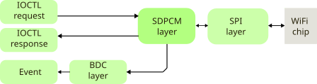
An IOCTL (Input/Output Control) call is sent by the Pico host CPU (RP2040) to the ARM CPU in the WiFi chip, to read or write configuration data, or send a specific command. An event is an unsolicited block of data sent from the WiFi CPU to the host; it can be a notification that an action is complete, or some data that has arrived over the WiFi network.
IOCTLs
A simple example of an IOCTL is a request for the 6-byte WiFi MAC address.
uint8_t mac[6];
ioctl_get_data("cur_etheraddr", 10, mac, 6);
This sends the IOCTL command GET_VAR, with a string to identify the item of interest, and a timeout in milliseconds.
#define WLC_GET_VAR 262

// Get data block from IOCTL variable
int ioctl_get_data(char *name, int wait_msec, uint8_t *data, int dlen)
{
    return(ioctl_cmd(WLC_GET_VAR, name, strlen(name)+1, wait_msec, false, data, dlen));
}
The request must be packed into a structure, for transmission the the WiFi CPU; this has 2 headers, the first is an ‘SDIO/SPI Bus Layer’ (SDPCM) header, followed by an IOCTL header:
// SDPCM header
typedef struct {
    uint16_t len,       // sdpcm_header.frametag
             notlen;
    uint8_t  seq,       // sdpcm_sw_header
             chan,
             nextlen,
             hdrlen,
             flow,
             credit,
             reserved[2];
} SDPCM_HDR;

// IOCTL header
typedef struct {
    uint32_t cmd;       // cdc_header
    uint16_t outlen,
             inlen;
    uint32_t flags,
             status;
} IOCTL_HDR;

// IOCTL command with SDPCM and IOCTL headers
typedef struct
{
    SDPCM_HDR sdpcm;
    IOCTL_HDR ioctl;
    uint8_t data[IOCTL_MAX_BLKLEN];
} IOCTL_CMD;
The first two 16-bit words of the SDPCM header contain the data length, and its bitwise inverse, then the most important fields are:
- Chan: a number identifying which ‘channel’ is associated with the data: IOCTL channel is 0, event is 1, and data is 2.
- Hdrlen: the length of the SDPCM header plus any padding. My code doesn’t use any padding, but the response from the WiFi chip often has a lot of padding.
- Flow & Credit: used to track the WiFi buffer utilisation
This is followed by the IOCTL header, with a command number (262 for GET_VAR) and a data length value.
The whole message plus data is written to the SPI interface:
// Do an IOCTL transaction, get response
// Return 0 if timeout, -1 if error response
int ioctl_cmd(int cmd, char *name, int namelen, int wait_msec, int wr, void *data, int dlen)
{
    IOCTL_CMD *cmdp = &ioctl_txmsg.cmd;
    int txdlen = ((namelen + dlen + 3) / 4) * 4, ret = 0;
    int hdrlen = sizeof(SDPCM_HDR) + sizeof(IOCTL_HDR);
    int txlen = hdrlen + txdlen;

    memset(cmdp, 0, sizeof(ioctl_txmsg));
    cmdp->sdpcm.notlen = ~(cmdp->sdpcm.len = txlen);
    cmdp->sdpcm.seq = sd_tx_seq++;
    cmdp->sdpcm.chan = SDPCM_CHAN_CTRL;
    cmdp->sdpcm.hdrlen = sizeof(SDPCM_HDR);
    cmdp->ioctl.cmd = cmd;
    cmdp->ioctl.outlen = txdlen;
    cmdp->ioctl.flags = ((uint32_t)ioctl_reqid++ << 16) | (wr ? 2 : 0);
    if (namelen)
        memcpy(cmdp->data, name, namelen);
    if (wr && dlen>0)
        memcpy(&cmdp->data[namelen], data, dlen);
    wifi_data_write(SD_FUNC_RAD, 0, (void *)cmdp, txlen);
    ..continued below..
The code now waits for a response, but it is important to note that the first response it receives may be associated with a completely different request, or network data. So it is essential to check that the response matches the command, and if not, keep on checking for a matching response.
    ..continued from above..
    while (wait_msec>=0 && !(ret=ioctl_resp_match(cmd, data, dlen)))
    {
        wait_msec -= IOCTL_POLL_MSEC;
        usdelay(IOCTL_POLL_MSEC * 1000);
    }
    return(ret);
}

// Read an ioctl response, match the given command, any command if 0
// Return 0 if no response, -1 if error response
int ioctl_resp_match(int cmd, void *data, int dlen)
{
    int rxlen=0, n=0, hdrlen;
    IOCTL_MSG *rsp = &ioctl_rxmsg;
    IOCTL_HDR *iohp;

    if ((rxlen = event_read(rsp, 0, 0)) > 0)
    {
        iohp = (IOCTL_HDR *)&rsp->data[rsp->cmd.sdpcm.hdrlen];
        hdrlen = rsp->cmd.sdpcm.hdrlen + sizeof(IOCTL_HDR);
        if (rsp->rsp.chan==SDPCM_CHAN_CTRL &&
            (cmd==0 || cmd==iohp->cmd))
        {
            n = MIN(dlen, rxlen-hdrlen);
            if (data && n>0)
                memcpy(data, &rsp->data[hdrlen], n);
            if (cmd)
            {
                if (iohp->status)
                    n = -1;
            }
        }
    }
    return(cmd==0 ? rxlen : n>0 ? n : 0);
}
You’ll note that the response has been obtained using the ‘event_read’ function, which handles all incoming data (solicited or unsolicited) from the WiFi interface; it will be described in detail below.
The IOCTL response has a similar format to the request, except that it generally has a lot of padding after the SDPCM header. This means that (unlike the transmit message) the receiver has to decode the SDPCM header ‘hdrlen’ value, in order to know how much padding has been added in front of the IOCTL header.
In addition to the IOCTL GET_VAR call that reads the value of a variable, given its name as a string, and its partner SET_VAR that writes a new value to that variable, there nearly 300 other IOCTL calls, such as SET_ANTDIV (command 64) which controls the antenna diversity, or UP (command 2) which is used to activate the WiFi interface.
Events
The WiFi chip signals an event when it has something to report to the host processor, for example it has succeeded in joining a WiFi network, or it has just received a data packet from that network.
As discussed above, there is a time-delay associated with any IOCTL command, so the IOCTL response might arrive within a stream of other events. So my code treats any incoming message as a potential event, and establishes its purpose by decoding the SDPCM header.
This raises the question of how the host CPU knows that there is an incoming event; the answer is that it can poll the BUS_SPI_STATUS_REG, to see if the ‘function 2 packet available’ flag is set. Alternatively, to avoid excessive polling cycles, the host can just check the IRQ line (described in part 1) and if that is high, there is an event pending. I use a combined approach; check the IRQ line, but is there hasn’t been any event for 10 milliseconds, check the status register:
#define SPI_STATUS_LEN_SHIFT            9
#define SPI_STATUS_LEN_MASK             0x7ff

// Get ioctl response, async event, or network data.
int event_get_resp(void *data, int maxlen)
{
    uint32_t val=0;
    int rxlen=0;

    val = wifi_reg_read(SD_FUNC_BUS, SPI_STATUS_REG, 4);
    if ((val != ~0) && (val & SPI_STATUS_PKT_AVAIL))
    {
        rxlen = (val >> SPI_STATUS_LEN_SHIFT) & SPI_STATUS_LEN_MASK;
        rxlen = MIN(rxlen, maxlen);
        // Read event data if present
        if (data && rxlen>0)
            wifi_data_read(SD_FUNC_RAD, 0, data, rxlen);
        // ..or clear interrupt, and discard data
        else
        {
            val = wifi_reg_read(SD_FUNC_BUS, SPI_INTERRUPT_REG, 2);
            wifi_reg_write(SD_FUNC_BUS, SPI_INTERRUPT_REG, val, 2);
            wifi_reg_write(SD_FUNC_BAK, SPI_FRAME_CONTROL, 0x01, 1);
        }
    }
    return(rxlen);
}
The status register has a flag to indicate data is available on function 2 (the radio interface), and also a length value, indicating how many bytes there are to read. Once that has been read in, the SDPCM header is checked, and the data after that header is copied into a buffer.
// Get ioctl response, async event, or network data
// Optionally copy data after SDPCM & BDC headers into a buffer, return its length
int event_read(IOCTL_MSG *rsp, void *data, int dlen)
{
    int rxlen=0, n=0, hdrlen;
    SDPCM_HDR *sdp=&rsp->cmd.sdpcm;
    BDC_HDR *bdcp;

    if ((rxlen = event_get_resp(rsp, sizeof(IOCTL_MSG))) >= sizeof(SDPCM_HDR)+sizeof(BDC_HDR))
    {
        if ((sdp->len ^ sdp->notlen) == 0xffff)
        {
            hdrlen = sdp->hdrlen;
            bdcp = (BDC_HDR *)&rsp->data[hdrlen];
            hdrlen += sizeof(BDC_HDR) + bdcp->offset*4;
            n = MIN(dlen, rxlen-hdrlen);
            if (data && n>0)
                memcpy(data, &rsp->data[hdrlen], n);
        }
    }
    return(dlen>0 ? (n>0 ? n : 0) : rxlen);
}
At the top of these function calls is the polling function, which stores the SDPCM values in a local structure (EVENT_INFO), and takes appropriate action with the data. The reason why a local structure is used is that the event header is in ‘network’ byte-order, which is big-endian (most-significant byte first), so the data is byte-swapped before being stored locally.
Since there may be multiple event handlers, and the the the polling function can’t know which one is the correct destination for the event, it calls each one in turn, stopping when one returns a non-zero value, indicating that it has accepted the event.
// Poll for async event, put results in info structure
int event_poll(void)
{
    EVENT_INFO *eip = &event_info;
    IOCTL_MSG *iomp = &ioctl_rxmsg;
    ESCAN_RESULT *erp=(ESCAN_RESULT *)rxdata;
    EVENT_HDR *ehp = &erp->eventh;
    int n = event_read(iomp, rxdata, sizeof(rxdata));

    if (n > 0)
    {
        eip->chan = iomp->rsp.sdpcm.chan;
        eip->flags = SWAP16(ehp->flags);
        eip->event_type = SWAP32(ehp->event_type);
        eip->status = SWAP32(ehp->status);
        eip->reason = SWAP32(ehp->reason);
        eip->data = rxdata;
        eip->dlen = n;
        if (eip->chan == SDPCM_CHAN_CTRL)
            display(DISP_EVENT, "\n");
        else if ((eip->chan==SDPCM_CHAN_EVT || eip->chan==SDPCM_CHAN_DATA) &&
            n >= sizeof(ETHER_HDR)+sizeof(BCMETH_HDR)+sizeof(EVENT_HDR))
            ok = event_handle(eip);
    }
    return(ok);
}
Handling an event
The code calls handler functions in turn, until one returns a non-zero value, indicating it has accepted the event.
#define MAX_HANDLERS    10
typedef int (*event_handler_t)(EVENT_INFO *eip);
event_handler_t event_handlers[MAX_HANDLERS];
int num_handlers;

// Run event handlers, until one returns non-zero
int event_handle(EVENT_INFO *eip)
{
    int ret=0;

    for (int i=0; i<num_handlers && !ret; i++)
        ret = event_handlers[i](eip);
    return(ret);
}
An event handler is called with a pointer to the EVENT_INFO structure, which basically contains a copy of the SDPCM header information (in the correct byte-order) and a pointer to the data after that header. The function must return zero if it hasn’t recognised the event. As an example, here is a simple handler that displays the result of a network scan:
// Handler for scan events
int scan_event_handler(EVENT_INFO *eip)
{
    ESCAN_RESULT *erp=(ESCAN_RESULT *)eip->data;
    int ret = eip->chan==SDPCM_CHAN_EVT && eip->event_type==WLC_E_ESCAN_RESULT;

    if (ret)
    {
        if (erp->eventh.status == 0)
        {
            printf("Scan complete\n");
            ret = -1;
        }
        else
        {
            printf("%s '", mac_addr_str(erp->info.bssid));
            disp_ssid(&erp->info.ssid_len);
            printf("' chan %d\n", SWAP16(erp->info.channel));
        }
    }
    return(ret);
}
Note that the ESCAN_RESULT data is in ‘network’ byte-order, so needs to be byte-swapped before being displayed.
This handler has to be added to the array of handlers using a function call:
add_event_handler(scan_event_handler);
This allows you to implement your own event handlers, in addition to, or instead of, the functions I have provided.
Enabling events
There are over 140 possible events, and by default they are disabled; we need to enable those we are interested in, such as network authentication & joining, so we can detect any problems.
The enabling process uses a (very large) bitfield, each bit indicating whether an event is enabled or disabled; the resulting byte array is sent to the WiFi CPU using an IOCTL call.
#define EVENT_MAX           208
#define SET_EVENT(msk, e)   msk[4 + e/8] |= 1 << (e & 7)

uint8_t event_mask[EVENT_MAX / 8];

// Enable events
int events_enable(const EVT_STR *evtp)
{
    memset(event_mask, 0, sizeof(event_mask));
    while (evtp->num >= 0)
    {
        if (evtp->num / 8 < sizeof(event_mask))
            SET_EVENT(event_mask, evtp->num);
        evtp++;
    }
    return(ioctl_set_data("bsscfg:event_msgs", 10, event_mask, sizeof(event_mask)));
}
I have used an unusual method to specify the events that are to be enabled; a macro is used to store the event number, and a string corresponding to the event name. This means that I can display event names (instead of numbers) on a diagnostic console, which is very useful to show any problems.
// Storage for event number, and string for diagnostics
typedef struct {
    int num;
    char *str;
} EVT_STR;
#define EVT(e)      {e, #e}

const EVT_STR join_evts[]={EVT(WLC_E_JOIN), EVT(WLC_E_ASSOC), EVT(WLC_E_REASSOC),
    EVT(WLC_E_ASSOC_REQ_IE), EVT(WLC_E_ASSOC_RESP_IE), EVT(WLC_E_SET_SSID),
    EVT(WLC_E_LINK), EVT(WLC_E_AUTH), EVT(WLC_E_PSK_SUP),  EVT(WLC_E_EAPOL_MSG),
    EVT(WLC_E_DISASSOC_IND), EVT(WLC_E_DISASSOC_IND), EVT(-1)};
In the next part of this project we’ll be scanning and joining a network.
| Project links | |
|---|---|
| Introduction | Project overview |
| Part 1 | Low-level interface; hardware & software |
| Part 2 | Initialisation; CYW43xxx chip setup |
| Part 3 | IOCTLs and events; driver communication |
| Part 4 | Scan and join a network; WPA security |
| Part 5 | ARP, IP and ICMP; IP addressing, and ping |
| Part 6 | DHCP; fetching IP configuration from server |
| Part 7 | DNS; domain name lookup |
| Part 8 | UDP server socket |
| Part 9 | TCP Web server |
| Part 10 | Web camera |
| Source code | Full C source code |
Copyright (c) Jeremy P Bentham 2022. Please credit this blog if you use the information or software in it.
