
In part 4, the wireless chip was connected to a WiFi network, so it can now send & receive data on that network, but we still have to encode the data for transmission, and decode it for reception.
We’re using a ‘full MAC’ chip, so all the low-level WiFi interfacing is handled within the chip. When transmitting, it encrypts our data, and adds the necessary 802.11 headers so that it will accepted by the network access point; when receiving, the headers are stripped off and the data is decrypted before being passed over to the Pico CPU.
This doesn’t just make our encoding & decoding tasks easier, it also ensures that the transmissions fully conform to the (exceedingly complex) 802.11 rules; if your interest is in creating non-standard wireless transmissions, then I’m afraid this project will be of no help.
TCP/IP
The suite of protocols used for data transmission over the Internet are generally known as Transmission Control Protocol / Internet Protocol, or TCP/IP. We’ll only be using a small subset of these protocols, and the initial task is just to handle Address Resolution Protocol (ARP) and Internet Control Message Protocol (ICMP). This will allow us to send & receive diagnostic ‘ping’ messages, and do some simple benchmarks by communicating with another system.
TCP/IP uses a three-tier addressing system; at the highest level, there are names with dotted notation, such as iosoft.blog or http://www.google.com. To access the computer at this address, two further steps are required:
- a Domain Name System (DNS) database lookup is used to convert the name into an Internet Protocol (IP) address, which has 4 numeric values in dotted notation, for example 192.168.5.1
- an Address Resolution Protocol (ARP) message is sent out on the network, with a request to convert the remote unit’s IP address into a Media Access and Control (MAC) address, which has 6 bytes, that are normally printed with a colon separator, e.g. 28:CD:C1:00:12:34
The first of these will be tackled in the next part of this project; for now, I’m assuming that the unit has obtained an IP address from somewhere, and knows the IP address of another unit it wishes to communicate with, for example the WiFi access point.
Address Resolution Protocol (ARP)
This is probably the simplest of all TCP/IP protocols; the unit broadcasts a request in a specific format, giving the IP address it wants to contact, and if any unit on the same ‘subnet’ has that address, then it will respond with its 6-byte MAC address. That is used for outgoing messages, but for incoming messages our unit must listen out for ARP broadcasts, and if a request matches its IP address, it should respond with the MAC address.
The ARP message format can be encapsulated within a C structure:
typedef unsigned char  BYTE;
typedef unsigned short WORD;
typedef unsigned int   DWORD;
typedef BYTE MACADDR[MACLEN];
typedef unsigned int IPADDR;

/* ***** ARP (Address Resolution Protocol) packet ***** */
typedef struct
{
    WORD hrd,           /* Hardware type */
         pro;           /* Protocol type */
    BYTE  hln,          /* Len of h/ware addr (6) */
          pln;          /* Len of IP addr (4) */
    WORD op;            /* ARP opcode */
    MACADDR  smac;      /* Source MAC addr */
    IPADDR   sip;       /* Source IP addr */
    MACADDR  dmac;      /* Destination MAC addr */
    IPADDR   dip;       /* Destination IP addr */
} ARPKT;
This is the first of many C structures for TCP/IP, and I’ve chosen to define 8, 16 and 32-bit values as BYTE, WORD and DWORD for clarity.
To broadcast this message, we need to add on Ethernet header, giving a source MAC address (the MAC address of our unit, as reported by the WiFi chip) the destination MAC address (broadcast, which is all-ones, i.e. FF:FF:FF:FF:FF:FF) and a protocol ID, which indicates that we’re sending an ARP packet.
/* Ethernet (DIX) header */
typedef struct {
    MACADDR dest;               /* Destination MAC address */
    MACADDR srce;               /* Source MAC address */
    WORD    ptype;              /* Protocol type or length */
} ETHERHDR;
#define PCOL_ARP    0x0806      /* Protocol type: ARP */
#define PCOL_IP     0x0800      /*                IP */
There are a lot of similarities between the higher level of wired (Ethernet) and wireless (802.11) protocols, so it makes sense that both use the same network address structure.
Creating an ARP request is really just a fill-in-the-blanks exercise:
#define HTYPE       0x0001  /* Hardware type: ethernet */
#define ARPPRO      0x0800  /* Protocol type: IP */
#define ARPREQ      0x0001  /* ARP request */
#define ARPRESP     0x0002  /* ARP response */

// Add Ethernet header to buffer, return byte count
WORD ip_add_eth(BYTE *buff, MACADDR dmac, MACADDR smac, WORD pcol)
{
    ETHERHDR *ehp = (ETHERHDR *)buff;

    MAC_CPY(ehp->dest, dmac);
    MAC_CPY(ehp->srce, smac);
    ehp->ptype = htons(pcol);
    return(sizeof(ETHERHDR));
}

// Create an ARP frame, return length
int ip_make_arp(BYTE *buff, MACADDR mac, IPADDR addr, WORD op)
{
    int n = ip_add_eth(buff, op==ARPREQ ? bcast_mac : mac, my_mac, PCOL_ARP);
    ARPKT *arp = (ARPKT *)&buff[n];

    MAC_CPY(arp->smac, my_mac);
    MAC_CPY(arp->dmac, op==ARPREQ ? bcast_mac : mac);
    arp->hrd = htons(HTYPE);
    arp->pro = htons(ARPPRO);
    arp->hln = MACLEN;
    arp->pln = sizeof(DWORD);
    arp->op  = htons(op);
    arp->dip = addr;
    arp->sip = my_ip;
    if (display_mode & DISP_ARP)
        ip_print_arp(arp);
    return(n + sizeof(ARPKT));
}

// Convert byte-order in a 'short' variable
WORD htons(WORD w)
{
    return(w<<8 | w>>8);
}
All network data is in big-endian format (most-significant byte first), but the RP2040 processor is little-endian, so the 16-bit values need to be byte-swapped.
To transmit the message, all that is needed is to add on the SDPCM layer for the WiFi chip, and copy it into an outgoing message buffer:
// Transmit an ARP frame
int ip_tx_arp(MACADDR mac, IPADDR addr, WORD op)
{
    int n = ip_make_arp(txbuff, mac, addr, op);

    return(ip_tx_eth(txbuff, n));
 }

// Send transmit data
int ip_tx_eth(BYTE *buff, int len)
{
    return(event_net_tx(buff, len));
}
// Transmit network data
int event_net_tx(void *data, int len)
{
    TX_MSG *txp = &tx_msg;
    int txlen = sizeof(SDPCM_HDR)+2+sizeof(BDC_HDR)+len;

    display(DISP_DATA, "Tx_DATA len %d\n", len);
    disp_bytes(DISP_DATA, data, len);
    display(DISP_DATA, "\n");
    txp->sdpcm.len = txlen;
    txp->sdpcm.notlen = ~txp->sdpcm.len;
    txp->sdpcm.seq = sd_tx_seq++;
    memcpy(txp->data, data, len);
    if (!wifi_reg_val_wait(10, SD_FUNC_BUS, SPI_STATUS_REG,
            SPI_STATUS_F2_RX_READY, SPI_STATUS_F2_RX_READY, 4))
        return(0);
    return(wifi_data_write(SD_FUNC_RAD, 0, (uint8_t *)txp, (txlen+3)&~3));
}
The transmit data length is rounded up to the nearest 4 bytes, as the WiFi DMA controller only works handles complete 4-byte words.
ARP reception
An incoming message will arrive as an ‘event’ from the WiFi chip, and a handler function first checks that it is valid:
// Handler for incoming ARP frame
int arp_event_handler(EVENT_INFO *eip)
{
    ETHERHDR *ehp=(ETHERHDR *)eip->data;

    if (eip->chan == SDPCM_CHAN_DATA &&
        eip->dlen >= sizeof(ETHERHDR)+sizeof(ARPKT) &&
        htons(ehp->ptype) == PCOL_ARP &&
        (MAC_IS_BCAST(ehp->dest) ||
         MAC_CMP(ehp->dest, my_mac)))
    {
        return(ip_rx_arp(eip->data, eip->dlen));
    }
    return(0);
}
If the incoming message is an ARP request, then the receiver function transmits an appropriate response. If it is a response, the resulting MAC address is saved, for use in future transmissions:
// Receive incoming ARP data
int ip_rx_arp(BYTE *data, int dlen)
{
    ETHERHDR *ehp=(ETHERHDR *)data;
    ARPKT *arp = (ARPKT *)&data[sizeof(ETHERHDR)];
    WORD op = htons(arp->op);

    if (arp->dip == my_ip)
    {
        if (op == ARPREQ)
            ip_tx_arp(ehp->srce, arp->sip, ARPRESP);
        else if (op == ARPRESP)
            ip_save_arp(arp->smac, arp->sip);
        return(1);
    }
    return(0);
}
Ping

Having obtained the 6-byte MAC address of a unit we wish to communicate with, what can we send to it? The obvious choice is a diagnostic ‘ping’, that echoes back the data we send, and measures the round-trip time.
Ping uses the Internet Control Message Protocol (ICMP), with an IP header for the address information:
/* ***** ICMP (Internet Control Message Protocol) header ***** */
typedef struct
{
    BYTE  type,         /* Message type */
          code;         /* Message code */
    WORD  check,        /* Checksum */
          ident,        /* Identifier */
          seq;          /* Sequence number */
} ICMPHDR;
#define ICREQ           8   /* Message type: echo request */
#define ICREP           0   /*               echo reply */

/* ***** IP (Internet Protocol) header ***** */
typedef struct
{
    BYTE   vhl,         /* Version and header len */
           service;     /* Quality of IP service */
    WORD   len,         /* Total len of IP datagram */
           ident,       /* Identification value */
           frags;       /* Flags & fragment offset */
    BYTE   ttl,         /* Time to live */
           pcol;        /* Protocol used in data area */
    WORD   check;       /* Header checksum */
    IPADDR sip,         /* IP source addr */
           dip;         /* IP dest addr */
} IPHDR;
#define PICMP   1           /* Protocol type: ICMP */
#define PTCP    6           /*                TCP */
#define PUDP   17           /*                UDP */
Creating an ICMP request largely consists of filling in the values within these structures, and adding some arbitrary data on the end, but there are some issues to bear in mind:
- As with ARP, all values are big-endian (most significant byte first) so byte-swaps are needed
- Potentially the IP message (known as a ‘datagram’) may travel very long distances, with a large number of ‘hops’ between computers, and each of these hops will have a maximum data size it can accommodate, which is known as a Maximum Transmission Unit (MTU). To allow a large datagram to be sent across a link with a smaller MTU, there is a technique called ‘IP fragmentation’, whereby the transmission is chopped up into smaller parts, and the parts are reassembled at the receiving end. For simplicity, we won’t initially support fragmentation, which means we have an MTU of around 1.5K bytes.
- There is a checksum across the IP header and ICMP data, and this is calculated using a method that performs identically on big-endian and little-endian processors.
/* Calculate TCP-style checksum, add to old value */
WORD add_csum(WORD sum, void *dp, int count)
{
    WORD n=count>>1, *p=(WORD *)dp, last=sum;

    while (n--)
    {
        sum += *p++;
        if (sum < last)
            sum++;
        last = sum;
    }
    if (count & 1)
        sum += *p & 0x00ff;
    if (sum < last)
        sum++;
    return(sum);
}
Ping reception
If the unit has received a unicast ICMP request, then it should return a response to the sender that basically copies everything in the request, but with the source & destination addresses swapped, and the message type changed from request to reply. Theoretically, the ICMP checksum needs to be re-computed, but as it is just a sum of 16-bit words, it isn’t affected by the address swap. So we can just re-use the existing checksum, adjusted for the change from the request value of 8 to the response value of 0:
// Receive incoming ICMP data
int ip_rx_icmp(BYTE *data, int dlen)
{
    ETHERHDR *ehp=(ETHERHDR *)data;
    IPHDR *ip = (IPHDR *)&data[sizeof(ETHERHDR)];
    ICMPHDR *icmp = (ICMPHDR *)&data[sizeof(ETHERHDR)+sizeof(IPHDR)];
    int n;

    if (display_mode & DISP_ICMP)
        ip_print_icmp(ip);
    if (icmp->type == ICREQ)
    {
        ip_add_eth(data, ehp->srce, my_mac, PCOL_IP);
        ip->dip = ip->sip;
        ip->sip = my_ip;
        icmp->check = add_csum(icmp->check, &icmp->type, 1);
        icmp->type = ICREP;
        n = htons(ip->len);
        return(ip_tx_eth(data, sizeof(ETHERHDR)+n+sizeof(ICMPHDR)));
    }
    else if (icmp->type == ICREP)
    {
        ping_rx_time = ustime();
    }
    return(0);
}
Example program: ping.c
This program generates pins every 2 seconds, and responds to incoming ping requests. It uses a hard-coded IP addresses, for itself and the target of the outgoing pings:
IPADDR myip   = IPADDR_VAL(192,168,1,165);
IPADDR hostip = IPADDR_VAL(192,168,1,1);
‘myip’ should be set to a suitable unused IP address on your subnet (e.g. 182.168.1 in the above example); you can check if an address is unused by pinging it.
‘hostip’ should be set to the address of another unit on the network that can accept pings, or the address of the WiFi Access Point.
You’ll also need to set the name & password for the WiFi network you are using:
// The hard-coded password is for test purposes only!!!
#define SSID                "testnet"
#define PASSWD              "testpass"
See the PicoWi introduction for a description of the build process, and the connection of a serial console to see the diagnostic messages.
The LED will flash rapidly for a few seconds until the device is connected to the network; it will then switch on when a ping is sent, and off when it is received; on my network, the ping time is generally quite short, so only a brief flash is visible if everything is working correctly.
Ping times
On an Ethernet network, it is usual to see fast & repeatable values for the ping round-trip time. However wireless networks aren’t as predictable, since all units that are on the same radio channels will be competing for air-time, not just with your network, but any other networks within range.
So the response time will vary, depending on the activity of any networks sharing the same WiFi channels; here is a a typical example of 20 pings, using the time reported on the Pico console:
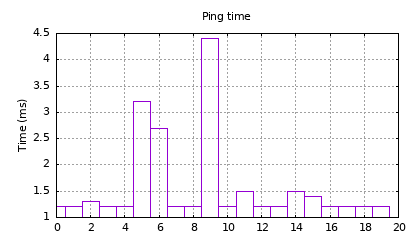
A ping time of 1.2 milliseconds is quite respectable, considering that a Pi 4 on the same network takes a minimum of 1.9 ms.
The graph was plotted using GNUplot; if you want to replicate it, the console output is captured to pings.txt, then pre-processed using awk:
awk -F [=\ ] '/time/ { print $(NF-1) }' pings.txt > pings.csv
This script should also work with the console output of Linux pings. The result is then fed to GNUplot; the command-line has been split into 4 for clarity:
gnuplot -e "set term png size 420,240 font 'sans,8'; \
  set title 'Ping time'; set grid; set key noautotitle; \
  set ylabel 'Time (ms)' offset 2; set output 'pings.png'; \
  plot 'pings.csv' with boxes"
| Project links | |
|---|---|
| Introduction | Project overview |
| Part 1 | Low-level interface; hardware & software |
| Part 2 | Initialisation; CYW43xxx chip setup |
| Part 3 | IOCTLs and events; driver communication |
| Part 4 | Scan and join a network; WPA security |
| Part 5 | ARP, IP and ICMP; IP addressing, and ping |
| Part 6 | DHCP; fetching IP configuration from server |
| Part 7 | DNS; domain name lookup |
| Part 8 | UDP server socket |
| Part 9 | TCP Web server |
| Part 10 | Web camera |
| Source code | Full C source code |
Copyright (c) Jeremy P Bentham 2022. Please credit this blog if you use the information or software in it.

Great series of articles! Could I ask why you wrote your own driver vs. using the one in the Pico SDK?
LikeLike
I need a fast WiFi interface for a new version of the EDLA project, and though this would just be a simple port of my Zerowi code. It has turned out to be much more complicated, but I wasn’t going to waste all that effort by giving up. I realise that in its present form the project isn’t much use (though it is significantly faster than the SDK version) but I have plans to extend the IP functionality, and test it in a real application.
LikeLike