Part 1: joining a network
The Raspberry Pi Pico is an incredibly useful low-cost micro-controller module based on the RP2040 CPU, but at the time of writing, there is a major omission: there is no networking capability.
This project adds low-cost wireless networking to the Pi Pico, and any other RP2040 boards. The There are various modules on the market that could be used for this purpose; I have chosen the Microchip ATWINC1500 or 1510 modules as they low-cost, have an easy hardware interface (4-wire SPI), and feature a built-in TCP/IP software stack, which significantly reduces the amount of software needed on the RP2040.
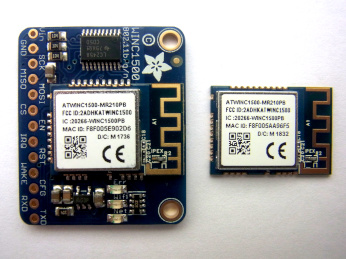
The photo above shows the module mounted on an Adafruit breakout board, and the module itself; this is the variant with a built-in antenna, but there is also a version with an antenna connector, that allows an external antenna to be used.
The only difference between the ATWINC1500 and 1510 modules is that the latter have larger flash memory size (1 MB, as opposed to 0.5 MB). There is also an earlier series of low-level interface modules named ATWILC; I’m not using them, as the built-in TCP/IP software of the ATWINC saves a lot of code complication on the RP2040.
Hardware connections

For simplicity, I have used the Adafruit breakout board, but it is possible to directly connect the module to the Pico, powered from its 3.3V supply.

Pi Pico pins
SCK     18     SPI clock
MOSI    19     SPI data out
MISO    16     SPI data in
CS      17     SPI chip select
WAKE    20     Module wake
EN      20     Module enable
RESET   21     Module reset
IRQ     22     Module interrupt request
No extra components are needed, if the wiring to the module is kept short, i.e. 3 inches (76 mm).
SPI on the RP2040
Initialising the SPI interface on the RP2040 just involves a list of API function calls:
#define SCK_PIN     18
#define MOSI_PIN    19
#define MISO_PIN    16
#define CS_PIN      17
#define WAKE_PIN    20
#define RESET_PIN   21
#define IRQ_PIN     22

// Initialise SPI interface
void spi_setup(int fd)
{
    stdio_init_all();
    spi_init(SPI_PORT, SPI_SPEED);
    spi_set_format(SPI_PORT, 8, SPI_CPOL_0, SPI_CPHA_0, SPI_MSB_FIRST);
    gpio_init(MISO_PIN);
    gpio_set_function(MISO_PIN, GPIO_FUNC_SPI);
    gpio_set_function(CS_PIN,   GPIO_FUNC_SIO);
    gpio_set_function(SCK_PIN,  GPIO_FUNC_SPI);
    gpio_set_function(MOSI_PIN, GPIO_FUNC_SPI);
    gpio_init(CS_PIN);
    gpio_set_dir(CS_PIN, GPIO_OUT);
    gpio_put(CS_PIN, 1);
    gpio_init(WAKE_PIN);
    gpio_set_dir(WAKE_PIN, GPIO_OUT);
    gpio_put(WAKE_PIN, 1);
    gpio_init(IRQ_PIN);
    gpio_set_dir(IRQ_PIN, GPIO_IN);
    gpio_pull_up(IRQ_PIN);
    gpio_init(RESET_PIN);
    gpio_set_dir(RESET_PIN, GPIO_OUT);
    gpio_put(RESET_PIN, 0);
    sleep_ms(1);
    gpio_put(RESET_PIN, 1);
    sleep_ms(1);
}
When using the standard SPI transfer API function, I found that occasionally the last data bit wasn’t being received correctly. The reason was that the API function returns before the transfer is complete; the clock signal is still high, and needs to go low to finish the transaction. To fix this, I inserted a loop that waits for the clock to go low, before negating the chip-select line.
// Do SPI transfer
int spi_xfer(int fd, uint8_t *txd, uint8_t *rxd, int len)
{
    gpio_put(CS_PIN, 0);
    spi_write_read_blocking(SPI_PORT, txd, rxd, len);
    while (gpio_get(SCK_PIN)) ;
    gpio_put(CS_PIN, 1);
}
Interface method
The WiFi module has its own processor, running proprietary code; it is supplied with a suitable binary image already installed, so will start running as soon as the module is enabled.

The module has a Host Interface (HIF) that the Pico uses for all communications; it is a Serial Peripheral Interface (SPI) that consists of a clock signal, incoming & outgoing data lines (MOSI and MISO), and a Chip Select, also known as a Chip Enable. The Pico initiates and controls all the HIF transfers, but the module can request a transfer by asserting an Interrupt Request (IRQ) line.
The module is powered up by asserting the ‘enable’ line, then briefly pulsing the reset line. This ensures that there is a clean startup, without any complications caused by previous settings.
There are 2 basic methods to transfer data between the PICO and the module; simple 32-bit configuration values can be transferred as register read/write cycles; there is a specific format for these, which includes an acknowledgement that a write cycle has succeeded. The following logic analyser trace shows a 32-bit value of 0x51 being read from register 0x1070; the output from the CPU is MOSI, and the input from the module is MISO.
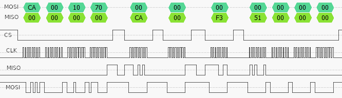
Now the corresponding write cycle, where the CPU is writing back a value of 0x51 to the same 32-bit register.

There are a few unusual features about these transfers.
- The chip-select (CS) line doesn’t have to be continuously asserted during the transfer, it need only be asserted whilst a byte is actually being read or written.
- The command value is CA hex for a read cycle, and C9 for a write.
- The module echoes back the command value plus 2 bytes for a read (CA 00 F3), or plus 1 byte for a write (C9 00), to indicate it has been accepted.
- The register address is 24-bit, big-endian (most significant byte first)
- The data value is 32-bit, little-endian in the read cycle (51 00 00 00), and big-endian in the write cycle (00 00 00 50).
The last point is quite remarkable, and when starting on the code development, I had great difficulty believing it could be true. The likely reason is that the SPI transfer is is big-endian as defined in the Secure Digital (SD) card specification, but the CPU in the module is little-endian. So the firmware has to either do a byte-swap on every response message, or return everything using the native byte-order, with this result.
In addition to reading & writing single-word registers, the software must read & write blocks of data. This involves some negotiation with the module firmware, since that manages the allocation & freeing of the necessary storage space in the module. For example, the procedure for a block write is:
- Request a buffer of the required size
- Receive the address of the buffer from the module
- Write one or more data blocks to the buffer
- Signal that the transfer is complete
Reading is similar, except that the first step isn’t needed, as the buffer is already available with the required data.
Operations
The above transfer mechanism is used to send commands to the module, and receive responses back from it; there is generally a one-to-one correspondence between the command and response, but there may be a significant delay between the two. For example, the ‘receive’ command requests a data block that has been received over the network, but if there is none, there will be no response, and the command will remain active until something does arrive.
The commands are generally referred to as ‘operations’, and they are split into groups:
- Main
- Wireless (WiFi)
- Internet Protocol (IP)
- Host Interface (HIF)
- Over The Air update (OTA)
- Secure Socket Layer (SSL)
- Cryptography (Crypto)
Each operation is assigned a number, and there is some re-use of numbers within different groups, for example a value of 70 in the WiFi group is used to enable Acess Point (AP) mode, but the same value in the IP group is a socket receive command. To avoid this possible source of confusion, my code combines the group and operation into a single 16-bit value, e.g.
// Host Interface (HIF) Group IDs
#define GID_MAIN        0
#define GID_WIFI        1
#define GID_IP          2
#define GID_HIF         3

// Host Interface operations with Group ID (GID)
#define GIDOP(gid, op) ((gid << 8) | op)
#define GOP_STATE_CHANGE    GIDOP(GID_WIFI, 44)
#define GOP_DHCP_CONF       GIDOP(GID_WIFI, 50)
#define GOP_CONN_REQ_NEW    GIDOP(GID_WIFI, 59)
#define GOP_BIND            GIDOP(GID_IP,   65)
..and so on..
To invoke an operation on the module, you must first send a 4-byte header that gives an 8-bit operation number, 8-bit group, and 16-bit message length.
typedef struct {
    uint8_t gid, op;
    uint16_t len;
} HIF_HDR;
The next 4 bytes of the message are unused, so can either be sent as zeros, or just skipped. Then there is the command header, which varies depending on the operation being performed, but are often 16 bytes or less, for example the IP ‘bind’ command:
// Address field for socket, network order (MSbyte first)
typedef struct {
    uint16_t family, port;
    uint32_t ip;
} SOCK_ADDR;

// Socket bind command, 12 bytes
typedef struct {
    SOCK_ADDR saddr;
    uint8_t sock, x;
    uint16_t session;
} BIND_CMD;
I’ll be discussing the IP operations in detail in the next part.
The interrupt request (IRQ) line is pulled low by the module to indicate that a response is available; for simplicity, my code polls this line, and calls an interrupt handler.
if (read_irq() == 0)
    interrupt_handler();
Joining a network
I’ll start with the most common use-case; joining a network that uses WiFi Protected Access (WPA or WPA2), and obtaining an IP address using Dynamic Host Configuration Protocol (DHCP). This is remarkably painless, since the module firmware does all of the hard work, but first we have to tackle the issue of firmware versions.
As previously explained, the module comes pre-loaded with firmware; at the time of writing, this is generally version 19.5.2 or 19.6.1. There is a provision for re-flashing the firmware to the latest version, but for the time being I’d like to avoid that complication, so the code I’ve written is compatible with both versions.
The reason that this matters is that 19.6.1 introduced a new method for joining a network, with a new operation number (59, as opposed to 40). Fortunately the newer software can still handle the older method, so that is what I’ll be using by default, though there is a compile-time option to use the new one, if you’re sure the module has the newer firmware.
The code to join the network is remarkably brief, just involving some data preparation, then calling a host interface transfer function to send the data. It searches across all channels to find a signal that matches the given Service Set Identifier (SSID, or network name). A password string (WPA passphrase) is also given; if this is a null value, the module will attempt to join an ‘open’ (insecure) network, but there are very obvious security risks with this, so it is not recommended.
// Join a WPA network, or open network if null password
bool join_net(int fd, char *ssid, char *pass)
{
#if NEW_JOIN
    CONN_HDR ch = {pass?0x98:0x2c, CRED_STORE, ANY_CHAN, strlen(ssid), "",
                   pass?AUTH_PSK:AUTH_OPEN, {0,0,0}};
    PSK_DATA pd;

    strcpy(ch.ssid, ssid);
    if (pass)
    {
        memset(&pd, 0, sizeof(PSK_DATA));
        strcpy(pd.phrase, pass);
        pd.len = strlen(pass);
        return(hif_put(fd, GOP_CONN_REQ_NEW|REQ_DATA, &ch, sizeof(CONN_HDR),
               &pd, sizeof(PSK_DATA), sizeof(CONN_HDR)));
    }
    return(hif_put(fd, GOP_CONN_REQ_NEW, &ch, sizeof(CONN_HDR), 0, 0, 0));
#else
    OLD_CONN_HDR och = {"", pass?AUTH_PSK:AUTH_OPEN, {0,0}, ANY_CHAN, "", 1, {0,0}};

    strcpy(och.ssid, ssid);
    strcpy(och.psk, pass ? pass : "");
    return(hif_put(fd, GOP_CONN_REQ_OLD, &och, sizeof(OLD_CONN_HDR), 0, 0, 0));
#endif
}
Running the code
There are 3 source files in the ‘part1’ directory on Github here:
- winc_pico_part1.c: main program, with RP2040-specific code
- winc_wifi.c: module interface
- winc_wifi.h: module interface definitions
The default network name and passphrase are “testnet” and “testpass”; these will have to be changed to match your network.
Normally I’d provide a simple Pi command-line to compile & run the files, but this is considerably more complex on the Pico; you’ll have to refer to the official documentation for setting up the development tools. I’ve provided a simple cmakelists file, that may need to be altered to suit your environment.
There is a compile-time ‘verbose’ setting, which regulates the amount of diagnostic information that is displayed on the console (serial link). Level 1 shows the following:
Firmware 19.5.2, OTP MAC address F8:F0:05:xx.xx.xx
Connecting...........
Interrupt gid 1 op 44 len 12 State change connected
Interrupt gid 1 op 50 len 28 DHCP conf 10.1.1.11 gate 10.1.1.101

[or if the network can't be found]
Interrupt gid 1 op 44 len 12 State change fail
Verbose level 2 lists all the register settings as well, e.g.
Rd reg 1000: 001003a0
Rd reg 13f4: 00000001
Rd reg 1014: 807c082d
Rd reg 207bc: 00003f00
Rd reg c000c: 00000000
Rd reg c000c: 10add09e
Wr reg 108c: 13521330
Wr reg 14a0: 00000102
..and so on..
Level 3 also includes hex dumps of the data transfers.
Socket interface
Part 2 describes the socket interface, with TCP and UDP servers here.
Copyright (c) Jeremy P Bentham 2021. Please credit this blog if you use the information or software in it.

Fascinating post, Jeremy. I looked up the cost of the ATWINC1500 module and it seems to vary wildly – as little as £6.50 plus VAT at Farnell and many 10s of £ on eBay This would not be an economic solution at the higher prices compared with ESP devices. Nothing yet from RPi on the ADC DNL problem on Pico.
LikeLike
The Ebay price is terrible; basically the vendor has no stock, and just does a heavy markup on the RS/Farnell/Mouser/Digikey price. Then when they get an order, they just buy the item in from a distributor, and ship it on with a sizeable profit. A sensible one-off price for the ATWINC1510 module is £6 to £7; not really cheap, but I think it does have some benefits when compared with the ESP parts – and it is much easier to program than the Broadcom part on the Pi zero!
LikeLike